Duetwifi board seems bad
-
@wild-bill-diamond try now
-
@jay_s_uk here is what I get
-
@wild-bill-diamond i've upvoted some more posts so give it another whirl
-
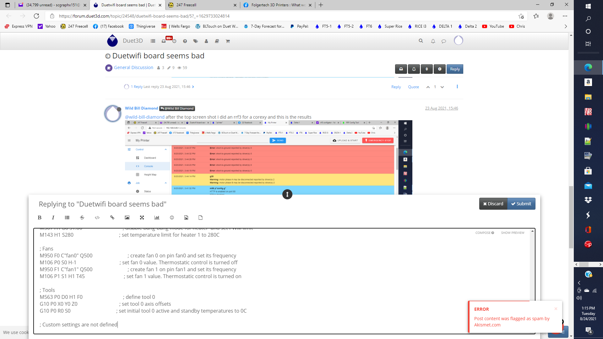
Configuration file for Duet WiFi (firmware version 3) ; executed by the firmware on start-up ; ; generated by RepRapFirmware Configuration Tool v3.3.0 on Mon Aug 23 2021 15:34:10 GMT-0700 (Pacific Daylight Time) ; General preferences G90 ; send absolute coordinates... M83 ; ...but relative extruder moves M550 P"My Printer" ; set printer name M669 K1 ; select CoreXY mode ; Network M552 S1 ; enable network M586 P0 S1 ; enable HTTP M586 P1 S0 ; disable FTP M586 P2 S0 ; disable Telnet ; Drives M569 P0 S1 ; physical drive 0 goes forwards M569 P1 S1 ; physical drive 1 goes forwards M569 P2 S1 ; physical drive 2 goes forwards M569 P3 S1 ; physical drive 3 goes forwards M584 X0 Y1 Z2 E3 ; set drive mapping M350 X16 Y16 Z16 E16 I1 ; configure microstepping with interpolation M92 X80.00 Y80.00 Z400.00 E420.00 ; set steps per mm M566 X900.00 Y900.00 Z60.00 E120.00 ; set maximum instantaneous speed changes (mm/min) M203 X6000.00 Y6000.00 Z180.00 E1200.00 ; set maximum speeds (mm/min) M201 X500.00 Y500.00 Z20.00 E250.00 ; set accelerations (mm/s^2) M906 X800 Y800 Z800 E800 I30 ; set motor currents (mA) and motor idle factor in per cent M84 S30 ; Set idle timeout ; Axis Limits M208 X0 Y0 Z0 S1 ; set axis minima M208 X230 Y210 Z200 S0 ; set axis maxima ; Endstops M574 X1 S1 P"xstop" ; configure active-high endstop for low end on X via pin xstop M574 Y1 S1 P"ystop" ; configure active-high endstop for low end on Y via pin ystop ; Z-Probe M558 P1 C"zprobe.in" H5 F120 T6000 ; set Z probe type to unmodulated and the dive height + speeds G31 P500 X0 Y0 Z2.5 ; set Z probe trigger value, offset and trigger height M557 X15:215 Y15:195 S20 ; define mesh grid ; Heaters M308 S0 P"bedtemp" Y"thermistor" T100000 B4138 ; configure sensor 0 as thermistor on pin bedtemp M950 H0 C"bedheat" T0 ; create bed heater output on bedheat and map it to sensor 0 M307 H0 B1 S1.00 ; enable bang-bang mode for the bed heater and set PWM limit M140 H0 ; map heated bed to heater 0 M143 H0 S120 ; set temperature limit for heater 0 to 120C M308 S1 P"e0temp" Y"thermistor" T100000 B4138 ; configure sensor 1 as thermistor on pin e0temp M950 H1 C"e0heat" T1 ; create nozzle heater output on e0heat and map it to sensor 1 M307 H1 B0 S1.00 ; disable bang-bang mode for heater and set PWM limit M143 H1 S280 ; set temperature limit for heater 1 to 280C ; Fans M950 F0 C"fan0" Q500 ; create fan 0 on pin fan0 and set its frequency M106 P0 S0 H-1 ; set fan 0 value. Thermostatic control is turned off M950 F1 C"fan1" Q500 ; create fan 1 on pin fan1 and set its frequency M106 P1 S1 H1 T45 ; set fan 1 value. Thermostatic control is turned on ; Tools M563 P0 D0 H1 F0 ; define tool 0 G10 P0 X0 Y0 Z0 ; set tool 0 axis offsets G10 P0 R0 S0 ; set initial tool 0 active and standby temperatures to 0C ; Custom settings are not defined -
Configuration file for Duet WiFi (firmware version 3) ; executed by the firmware on start-up ; ; generated by RepRapFirmware Configuration Tool v3.3.0 on Mon Aug 23 2021 15:34:10 GMT-0700 (Pacific Daylight Time) ; General preferences G90 ; send absolute coordinates... M83 ; ...but relative extruder moves M550 P"My Printer" ; set printer name M669 K1 ; select CoreXY mode ; Network M552 S1 ; enable network M586 P0 S1 ; enable HTTP M586 P1 S0 ; disable FTP M586 P2 S0 ; disable Telnet ; Drives M569 P0 S1 ; physical drive 0 goes forwards M569 P1 S1 ; physical drive 1 goes forwards M569 P2 S1 ; physical drive 2 goes forwards M569 P3 S1 ; physical drive 3 goes forwards M584 X0 Y1 Z2 E3 ; set drive mapping M350 X16 Y16 Z16 E16 I1 ; configure microstepping with interpolation M92 X80.00 Y80.00 Z400.00 E420.00 ; set steps per mm M566 X900.00 Y900.00 Z60.00 E120.00 ; set maximum instantaneous speed changes (mm/min) M203 X6000.00 Y6000.00 Z180.00 E1200.00 ; set maximum speeds (mm/min) M201 X500.00 Y500.00 Z20.00 E250.00 ; set accelerations (mm/s^2) M906 X800 Y800 Z800 E800 I30 ; set motor currents (mA) and motor idle factor in per cent M84 S30 ; Set idle timeout ; Axis Limits M208 X0 Y0 Z0 S1 ; set axis minima M208 X230 Y210 Z200 S0 ; set axis maxima ; Endstops M574 X1 S1 P"xstop" ; configure active-high endstop for low end on X via pin xstop M574 Y1 S1 P"ystop" ; configure active-high endstop for low end on Y via pin ystop ; Z-Probe M558 P1 C"zprobe.in" H5 F120 T6000 ; set Z probe type to unmodulated and the dive height + speeds G31 P500 X0 Y0 Z2.5 ; set Z probe trigger value, offset and trigger height M557 X15:215 Y15:195 S20 ; define mesh grid ; Heaters M308 S0 P"bedtemp" Y"thermistor" T100000 B4138 ; configure sensor 0 as thermistor on pin bedtemp M950 H0 C"bedheat" T0 ; create bed heater output on bedheat and map it to sensor 0 M307 H0 B1 S1.00 ; enable bang-bang mode for the bed heater and set PWM limit M140 H0 ; map heated bed to heater 0 M143 H0 S120 ; set temperature limit for heater 0 to 120C M308 S1 P"e0temp" Y"thermistor" T100000 B4138 ; configure sensor 1 as thermistor on pin e0temp M950 H1 C"e0heat" T1 ; create nozzle heater output on e0heat and map it to sensor 1 M307 H1 B0 S1.00 ; disable bang-bang mode for heater and set PWM limit M143 H1 S280 ; set temperature limit for heater 1 to 280C ; Fans M950 F0 C"fan0" Q500 ; create fan 0 on pin fan0 and set its frequency M106 P0 S0 H-1 ; set fan 0 value. Thermostatic control is turned off M950 F1 C"fan1" Q500 ; create fan 1 on pin fan1 and set its frequency M106 P1 S1 H1 T45 ; set fan 1 value. Thermostatic control is turned on ; Tools M563 P0 D0 H1 F0 ; define tool 0 G10 P0 X0 Y0 Z0 ; set tool 0 axis offsets G10 P0 R0 S0 ; set initial tool 0 active and standby temperatures to 0C ; Custom settings are not defined -
That config file looks pretty clean. I can't see why it would be generating those errors when you run M98 P"config.g"
Just to be sure, the config.g you copied and pasted is in the system folder? Some of the values don't seem to match the echoed values in your screen shots.
The short to ground and phase errors on the drivers might indicate incorrect wiring of the steppers. Verify the phase pairs with this.
-
@phaedrux I tested my motor wires and all was good, but when I tried to test a motor, same results. What I would like to do is box up the boards and send them to the experts and let them look at the boards. If they are bad because of something I did just throw in trash, and if just bad I would like replacements. I will pay all postage, I just need an address. I found another board I had and it is working just fine on the printer. Over the last several years I have ordered around 10 boards a couple of dx boards and a smart effector. Everything has worked perfect until these last 2 boards.
William Rice
Thank you for any help you can give me. -
Well before we do that let's give it one more try.
Can you start with a screen shot of the SD card folder structure? I'm mostly interested with what's in the root of the card and the sys and macros folders.
Then in DWC go to the system tab and edit the config.g and confirm that it matches the one you posted above.
Next, please reflash the firmware and other files by uploading this single zip file to the system tab in DWC.
https://github.com/Duet3D/RepRapFirmware/releases/download/3.3/Duet2and3Firmware-3.3.zip
After it reboots, please send M122 and M98 P"config.g" and copy and paste the test of the results here.
If you still get phase and short to ground errors when trying to home the printer then we will take it from there down the warranty route.
-
@phaedrux I just tried something and it worked. What I did was I had a dx2 board I hooked up. I'm using X as the test motor. On the dx2 it worked perfect and with the same commands on the main board it went to ground like before. So I'm sure the board is bad
-
@wild-bill-diamond I'm pretty sure I might have caused the problem because of the way I had them mounted, so I'm calling this case closed. Just a $300 learning error
Thanks for all your help
-
I don't understand. What was the problem?
-
@phaedrux I had the board mounted on a 2020 with plastic spacers and the other end with some tall spacers and I thought it was level enough but I guess not. This happened with 2 boards from the get go. I put a hair line fracture in the board. I figured it out this morning when this 1 board wasn't light up like it should and I put a little pressure on the board with a finger and everything worked ok. So I'm blaming me for doing a poor job of mounting the board. I just want to say thank you for working with me on the problem. I love the duet I have 2 delta, I3 and 4 corexy. I'm retired and I do this for a hobby. I have 3 printers, scratch built from the ground. So again thank you for the help.
William Rice
-
Ah, sorry to hear that. Glad we figured it out I suppose, but not the solution I'd hoped.
-
@wild-bill-diamond I suspect the problem may be a bad solder joint rather than a hairline crack (assuming that you can't see a crack) and may therefore be recoverable. I suggest you start by examining visually using magnification the solder joints of the driver 3 TMC2660 chip and the surrounding components.
It may also be helpful to see a full M122 response that includes the driver 3 status.