#- (hash) printer with super simple gantry
-
@o_lampe oh yeah, I remember now. Never mind...
-
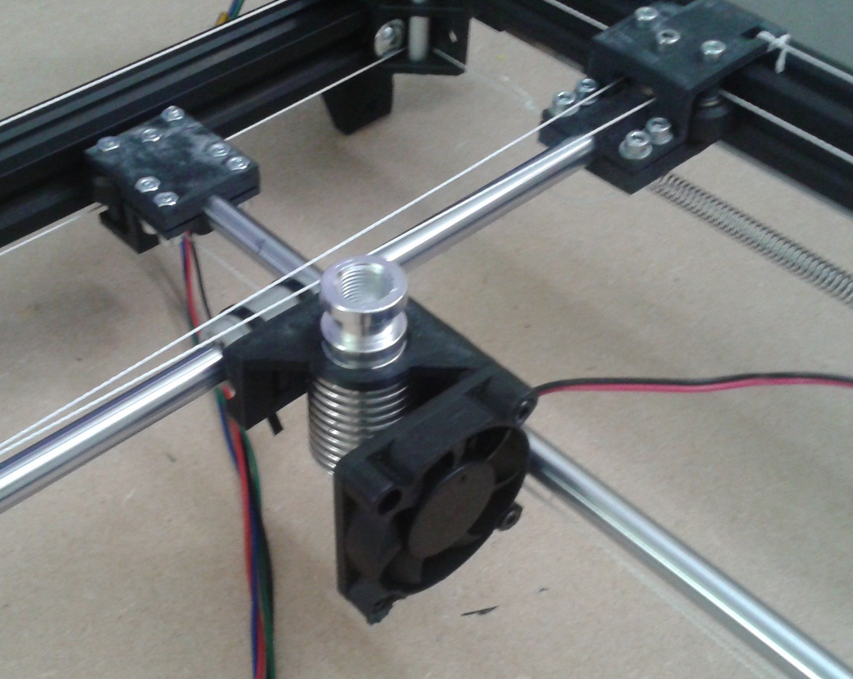
First Toolholder for an E3D heatsink. I can add a sherpa mini or bowden extruder.
-
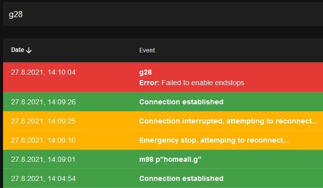
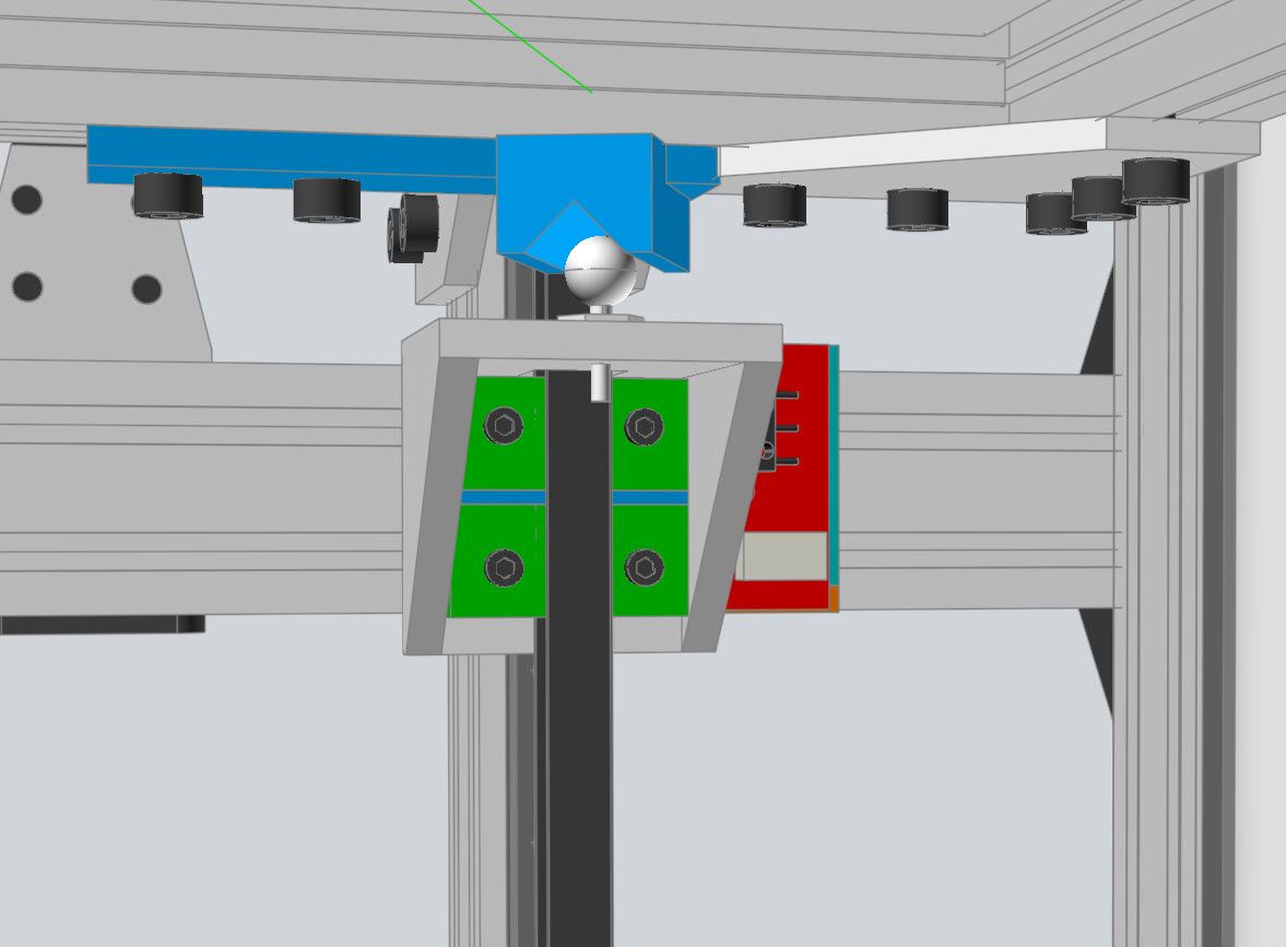
I've installed two beam braker endstops and wrote homing files.
They work fine, when called independently, but using homeall throws an error. "Failed to enable endstops"
Here's a homing file (check out, how I define/invert and delete the endstop); homeU.g M574 U2 S1 P"Xmax" ; change endstop M400 G91 ; relative positioning ;G1 H2 Z5 F6000 ; lift Z relative to current position G1 H1 U295 F6000 ; move quickly to X axis endstop and stop there (first pass) M574 U2 S1 P"!Xmax" ; change endstop M400 G1 H1 U29 F360 ; move slowly to x axis endstop once more (second pass) G92 U0 ;G1 H2 Z-5 F6000 ; lower Z again G90 ; absolute positioning M574 U2 S1 P"Nil" ; delete endstop M400 G1 U-130 F24000Homeall just calles all macros one by one, so where's my mistake?
; homeall.g
; called to home all axes
;
m98 p"homeX.g"
m98 p"homeY.g"
m98 p"homeU.g"
m98 p"homeV.g"
;G1 Z5 F100           ; lift Z relative to current position
G90                  ; absolute positioning
RRF3.3.0_6 on a F407ZG controller
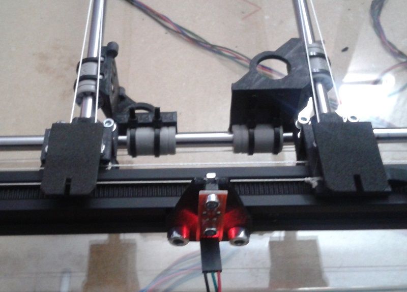
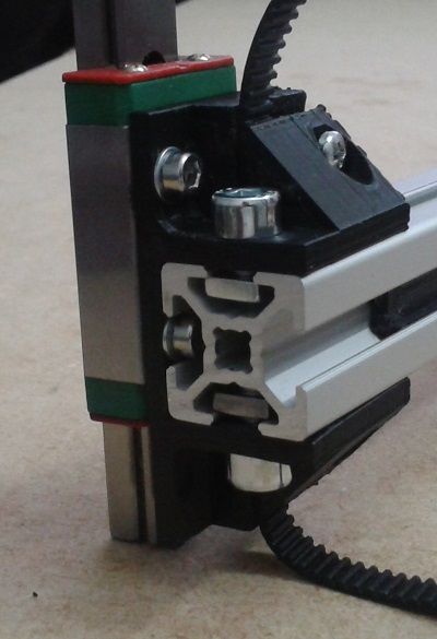
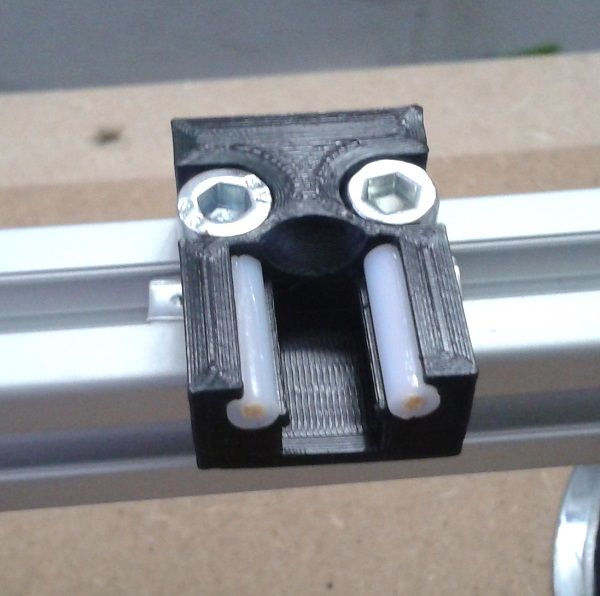
Here's a pic of the endstop with the extra cutout
-
@o_lampe what's in your other home macros? Can you please post them?
-
@cosmowave they're almost the same, except the specific parking positions and neg/pos signs of the homing moves.
; homeV.g M574 V2 S1 P"ymax" ; define endstop M400 G91 ; relative positioning ;G1 H2 Z5 F6000 ; lift Z relative to current position G1 H1 V-295 F6000 ; move quickly to Y axis endstop and stop there (first pass) M574 V2 S1 P"!ymax" ; invert endstop M400 G1 H1 V-29 F360 ; move slowly to Y axis endstop once more (second pass) G92 V0 ;G1 H2 Z-5 F6000 ; lower Z again G90 ; absolute positioning M574 V2 S1 P"nil" ; delete endstop M400 G1 V170 F24000 ; homeX.g M574 X2 S1 P"Xmax" ; change endstop M400 G91 ; relative positioning ;G1 H2 Z5 F6000 ; lift Z relative to current position G1 H1 X295 F6000 ; move quickly to x axis endstop and stop there (first pass) M574 X2 S1 P"!Xmax" ; change endstop M400 G1 H1 X29 F360 ; move slowly to x axis endstop once more (second pass) G92 X0 ;G1 H2 Z-5 F6000 ; lower Z again G90 ; absolute positioning M574 X2 S1 P"Nil" ; delete endstop M400 G1 X-185 F24000 ; homey.g M574 Y2 S1 P"ymax" ; change endstop M400 G91 ; relative positioning ;G1 H2 Z5 F6000 ; lift Z relative to current position G1 H1 Y295 F6000 ; move quickly to Y axis endstop and stop there (first pass) M574 Y2 S1 P"!ymax" ; change endstop M400 G1 H1 Y29 F360 ; move slowly to Y axis endstop once more (second pass) G92 Y0 ;G1 H2 Z-5 F6000 ; lower Z again G90 ; absolute positioning M574 Y2 S1 P"Nil" ; delete endstop M400 G1 Y-174 F24000 -
@o_lampe I'm not sure if the command M400 after setting/deleting the endstop will work correctly!? Perhaps it helps to change it to a short delay with G4?
-
that's funny: I send m98 P"homeall.g" and no error pops up, I reset the printer and send "G28" and the error is back.
@cosmowave m400 or g4 p100 made no difference, G4 only slows things down
-
Just out of curiosity why do you need to change the way the endstop works between the first and second pass?
Frederick
-
@fcwilt
there's a cutout at the center of the tongue that triggers the endstop during the slow pass.
The first pass detects the left or right edge of the tongue, then I invert the logic of the endstop and do the second pass. That way both tools set their homing point to the center of their tongue.
It's not mandatory to do it that way. Later, I have to fine tune the 0,0 position of every tool anyway. -
@o_lampe said in #- (hash) printer with super simple gantry:
@fcwilt
there's a cutout at the center of the tongue that triggers the endstop during the slow pass.
The first pass detects the left or right edge of the tongue, then I invert the logic of the endstop and do the second pass. That way both tools set their homing point to the center of their tongue.
It's not mandatory to do it that way. Later, I have to fine tune the 0,0 position of every tool anyway.Could you arrange homing so that the sensor was not triggered after homing was complete?
If so it would seem you could connect the sensor to two different inputs and not have to deal with changing the endstop settings.
Frederick
-
@fcwilt said in #- (hash) printer with super simple gantry:
connect the sensor to two different inputs and not have to deal with changing the endstop settings.
Sounds, like it would provoke false triggers to the not_homed axis or raising a endstop hit flag ?
The correct way seems to be to completely undefine the endstop to make it usable for the next tool. -
@o_lampe said in #- (hash) printer with super simple gantry:
@fcwilt said in #- (hash) printer with super simple gantry:
connect the sensor to two different inputs and not have to deal with changing the endstop settings.
Sounds, like it would provoke false triggers to the not_homed axis or raising a endstop hit flag ?
The correct way seems to be to completely undefine the endstop to make it usable for the next tool.Well unless there is a G1 H1 move underway for a given axis I've never seen endstop activation have any effect.
Though I think I will do some tests just for fun.
Frederick
-
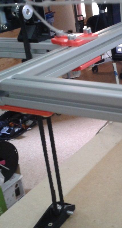
Another update.
I thought the triple Z-axis/bed frame would be a piece of cake to build, but it was tricky to find a place for steppers and belt-idlers.
It ended up in an ugly mess, but I'd have to redesign almost the whole printer to get it right. It's working, so I keep it as is until I find a real reason to rebuild it.
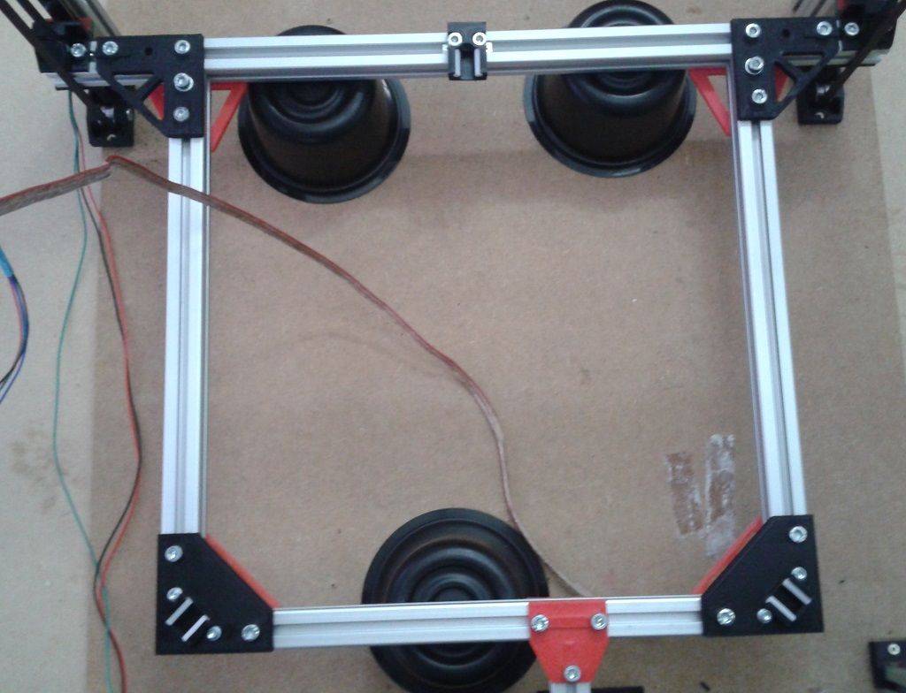
Pretty compact carrier
Top view. All tools are outside of the bed, which will be mounted above the frame. The 500x500 outside dimension shrinks to 300x300 working area, but that was expected.

The third Z-stepper needs an appendix to clear the tool path and still stabilize the far end of the cantilevered bed frame.
-
I want to design a tripod bed mount where the bed rests on three ballstuds sliding on dowel-pins to allow temp-expansion.
I"ve seen this on other printers, but I'm unsure about the angles of the dowel pins?Q: Should they aim to the bed-center, or should I place them at equal angles?
Here's a sketch of the angles in question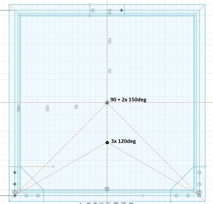
-
I went for Maxwell temp-expansion layout, simply because I couldn't make up a way to fix one side without melting the bracket.
Now I've used Haydn's ballstuds and 4mm PTFE tube as dowel pins. I guess that PTFE keeps the heat away from the brackets, better than (stainless) steel dowel pins.
I also filled the PTFE tube with pieces of wooden toothpicks to avoid sinking balls (pun intended)
PS: magnets will arrive monday, I hope they fit in their pocket.
-
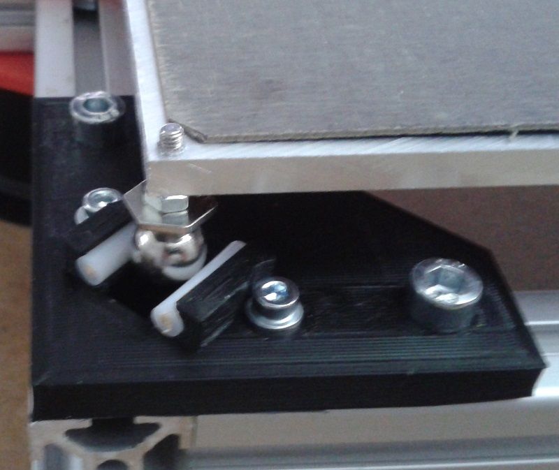
I did something like your setup but my rear support is a ball-stud sitting in a cup.
Frederick
-
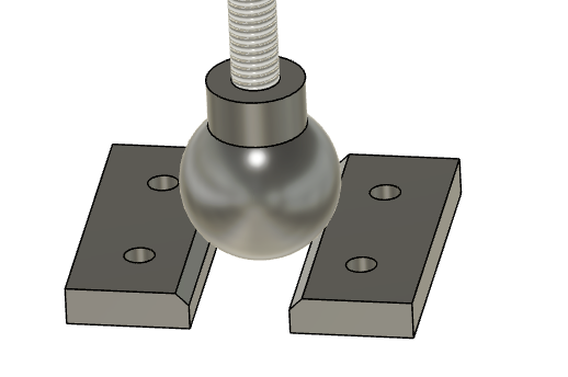
We're using kinematic supports for the heated bed on a large printer we are designing at my local maker space. We started with the classic steel ball and parallel rod design, but questioned the steel rods. They provide a parallel point landings for the steel ball. This means that the round cross section is not important - the steel ball touches only at a point. After trying a few things we opted for two small rectangular steel plates (1.5mm thick) that we files a 45 degree slope on. We screw these to the bottom of the heated bed. Here's a sketch from our F360 design.
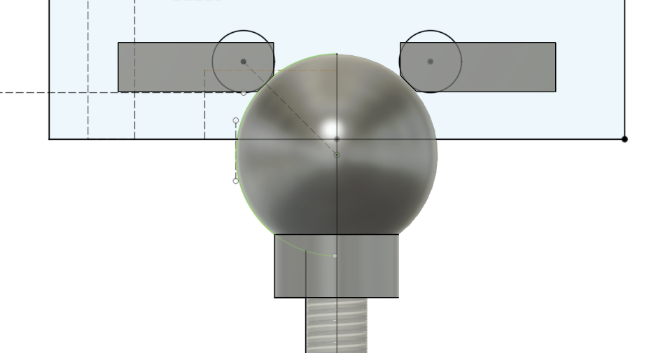
Next point - We are using the steel balls because we already bought them, but in the future I'd replace these with acorn nuts. I think just as good, easier to find, and much cheaper.
Next point - If one of your kinematic supports is a ball and cup, it locks in two directions of motion, but not rotation. The other two joints need to be different. One of the two should have one parallel sliding joint (with the sliding axis going through the center of the cup. This joint provides a lock to rotation. The last joint should be a ball sitting on a plane. It only provides a Z support. If you make either of these joints constrain more movement than this, you will not have a true kinematic connection. Sort of anal and pedantic, but if you go down the kinematic connection path...
Last point - I think keeping the balls on 120degree lines from a common center point, with the direction of sliding at each joint going through the center point, you will have the best solution.
-
@mikeabuilder @fcwilt
you both describe a Kelvin mount. I opted against it, because I wanted to have three identical ball-guides.A filed 45° corner would have to be perfectly machined. The Acorn nuts will drive you crazy, because they are only casted with high tolerances. (They are produced for the looks, not for accuracy)
The 120° approach would be easy to implement on a circular bed on a Delta frame, but a square bed frame ends in 90+2x150° angles. Not too bad, 'cause we don't need equal expansion.The whole build is experimental, I expect more trouble with the XY gantry. (and slicer/firmware issues)
-
I made a short demo video as appetizer for things to come.
It shows how two tools can draw different shapes at the same time. The other two tools can draw other shapes, but not at the same time.
Four tools could draw/print the same pattern simultaneously, eg. the four feet of The Eiffel tower. That would even be easier to slice and postprocess...
I'm using feltpens for now, but with extruders it would be ready to 3D print. (adjustment of individual Z-height per tool is important then) -
@o_lampe said in #- (hash) printer with super simple gantry:
@fcwilt
you both describe a *[Kelvin mount]After reading about the different kinds of mounts I decided to follow your lead.
I modified my printer to use a mount similar to yours.
My bed is supported by a frame made from 20x20 extrusions and the mounting points are on the frame well away from the heat of the bed.
I now have three one piece printed parts with a V for the ball to ride in.
They seem to be working fine.
Here is one of them:
Thanks for leading me to a better design.
Frederick
Printers: a small Utilmaker style, a small CoreXY and a E3D MS/TC setup. Various hotends. Using Duet 3 hardware running 3.4.6