toolboard print fan issue
-
hey cummunity
I have the problem that the print cooling fan isn´t working (at the moment I just have one tool in use).maybe anybody has a solution for it. would be very great!

-I´m using cura.
-extruder fan is working fine
-using original e3d 12v fans.thanks to all who takes time for support.
; Configuration file for Duet 3 (firmware version 3)
; executed by the firmware on start-up
;
; generated by RepRapFirmware Configuration Tool v3.2.3 on Mon Aug 02 2021 16:15:35 GMT+0200 (Mitteleuropäische Sommerzeit)

; General preferences
G90                                                        ; send absolute coordinates...
M83                                                        ; ...but relative extruder moves
M550 P"Duet 3"                                             ; set printer name

M552 S1 P192.168.2.108                                     ; Wifi
G4 S4
M574 C1 S3
M574 C0 Z0  						; No C Z endstop
M915 P1.2 C S0 F0 R1

; Drives
M569 P0.0 S1                                               ; physical drive 0.0 goes forwards
M569 P0.1 S1                                               ; physical drive 0.1 goes forwards
M569 P0.2 S0                                               ; physical drive 0.2 goes forwards
M569 P0.3 S0                                               ; physical drive 0.2 goes forwards
M569 P0.4 S0                                               ; physical drive 0.2 goes forwards
M569 P0.5 S0                                               ; physical drive 0.2 goes forwards
M569 P1.0 S0                                               ; physical drive 0.2 goes forwards
M569 P1.2 S0                                               ; physical drive 0.2 goes forwards
M569 P121.0 S0                                             ; physical drive 121.0 goes forwards
M569 P122.0 S1                                             ; physical drive 122.0 goes forwards
M569 P123.0 S1                                             ; physical drive 123.0 goes forwards
M584 X1.0 Y0.0:0.1 Z0.2:0.3:0.4:0.5 C1.2 E121.0:122.0:123.0     ; set drive mapping
M350 X16 Y16 Z16 E16:16:16 I1                              ; configure microstepping with interpolation
M92 X160.00 Y160.00 Z640.00 C91.022 E409.00:409.00:409.00          ; set steps per mm
M566 X300.00 Y300.00 Z60.00 C3000 E3.00:3.00:3.00       ; set maximum instantaneous speed changes (mm/min)
M203 X15000.00 Y15000.00 Z800.00 C5000 E6000.00:6000.00:6000.00 ; set maximum speeds (mm/min)
M201 X3000.00 Y3000.00 Z800.00 C400 E2500.00:2500.00:2500.00         ; set accelerations (mm/s^2)
M906 X1300 Y1300 Z2500 C400 E1000:1000:1000 I30                 ; set motor currents (mA) and motor idle factor in per cent
M84 S30                                                    ; Set idle timeout
M671 X-80:-80:930:930 Y-80:930:930:-80 S20 ; leadscrews at front left1 and n´back2. back rigth3 and front4

; Axis Limits
M208 X-10 Y-81.4 Z0 S1                                      ; set axis minima
M208 X860 Y890 Z850 S0                                  ; set axis maxima

; Endstops
M574 X2 S1 P"^io3.in"                                      ; configure active-high endstop for high end on X via pin ^io3.in
M574 Y2 S1 P"^io1.in"                                      ; configure active-high endstop for high end on Y via pin ^io1.in

; Z probe
M558 P5 C"io2.in" H50 F360 I0 T1100 	; Set Z probe type to switch, the axes for which it is used and the dive height + speeds
G31 P200 X5 Y30 Z0	 				; Set Z probe trigger value, offset and trigger height; Z probe
M556 S50 X0 Y0 Z0                                         ; set orthogonal axis compensation parameters
M557 X200:650 Y200:650 S45                             ; define mesh grid


; Heaters
M308 S0 P"temp0" Y"thermistor" T100000 B4138               ; configure sensor 0 as thermistor on pin temp0
M950 H0 C"out0" T0                                         ; create bed heater output on out0 and map it to sensor 0
 M307 H0 B0 R0.243 C586.2 D33.87 S1.00 V0                   ; disable bang-bang mode for the bed heater and set PWM limit
M140 H0                                                    ; map heated bed to heater 0
M143 H0 S120                                               ; set temperature limit for heater 0 to 120C
M308 S1 P"121.temp0" Y"thermistor" T100000 B4138           ; configure sensor 1 as PT1000 on pin 121.temp0
M950 H1 C"out1" T1                                         ; create nozzle heater output on out1 and map it to sensor 1
M307 H1 B0 S1.00                                           ; disable bang-bang mode for heater  and set PWM limit
M143 H1 S250                                               ; set temperature limit for heater 1 to 250C
M308 S2 P"122.temp0" Y"pt1000" R2200                       ; configure sensor 2 as PT1000 on pin 122.temp0
M950 H2 C"122.out0" T2                                     ; create nozzle heater output on 122.out0 and map it to sensor 2
M307 H2 B0 S1.00                                           ; disable bang-bang mode for heater  and set PWM limit
M143 H2 S250                                               ; set temperature limit for heater 2 to 250C
M308 S3 P"123.temp0" Y"pt1000" R2200                       ; configure sensor 3 as PT1000 on pin 123.temp0
M950 H3 C"123.out0" T3                                     ; create nozzle heater output on 123.out0 and map it to sensor 3
M307 H3 B0 S1.00                                           ; disable bang-bang mode for heater  and set PWM limit
M143 H3 S250                                               ; set temperature limit for heater 3 to 250C

; Fans
M950 F0 C"121.out1" Q500                                   ; create fan 0 on pin 121.out1 and set its frequency
M106 P0 S0 H-1                                             ; set fan 0 value. Thermostatic control is turned off
M563 P0 D0 H1                                              ; tool uses extruder 0, heater 1
M950 F1 C"121.out2" Q500                                   ; create fan 1 on pin 121.out2 and set its frequency
M106 P1 S1 H1 T45                                          ; set fan 1 value. Thermostatic control is turned on
M563 P0 D0 H1 F1                                           ; tool uses extruder 0, heater 1
M950 F2 C"122.out1" Q500                                   ; create fan 2 on pin 122.out1 and set its frequency
M106 P2 S1 H-1                                             ; set fan 2 value. Thermostatic control is turned off
M950 F3 C"122.out2" Q500                                   ; create fan 3 on pin 122.out2 and set its frequency
M106 P3 S1 H2 T45                                          ; set fan 3 value. Thermostatic control is turned on
M950 F4 C"123.out1" Q500                                   ; create fan 4 on pin 123.out1 and set its frequency
M106 P4 S1 H-1                                             ; set fan 4 value. Thermostatic control is turned off
M950 F5 C"123.out2" Q500                                   ; create fan 5 on pin 123.out2 and set its frequency
M106 P5 S1 H3 T45                                          ; set fan 5 value. Thermostatic control is turned on
M950 F6 C"out4" Q500                                       ; create fan 6 on pin out4 and set its frequency
M106 P6 S1 H-1                                             ; set fan 6 value. Thermostatic control is turned off
M950 F7 C"out5" Q500                                       ; create fan 7 on pin out5 and set its frequency
M106 P7 S1 H T45                                           ; set fan 7 value. Thermostatic control is turned on

; Tools
M563 P0 D0 H1                                              ; define tool 0
G10 P0 X30 Y28.25 Z-39.75                                  ; set tool 0 axis offsets
G10 P0 R0 S0                                               ; set initial tool 0 active and standby temperatures to 0C
M563 P1 D1 H2 F2                                           ; define tool 1
G10 P1 X0 Y0 Z0                                            ; set tool 1 axis offsets
G10 P1 R0 S0                                               ; set initial tool 1 active and standby temperatures to 0C
M563 P2 D2 H3 F4                                           ; define tool 2
G10 P2 X0 Y0 Z0                                            ; set tool 2 axis offsets
G10 P2 R0 S0                                               ; set initial tool 2 active and standby temperatures to 0C

; Custom settings are not defined

; Miscellaneous
M911 S10 R11 P"M913 X0 Y0 G91 M83 G1 Z3 E-5 F1000"         ; set voltage thresholds and actions to run on power loss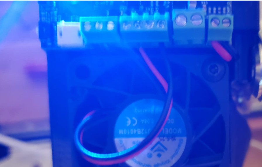
-
additional
1.dwc shows the right amount for print cooling...
2.he dwc shows fan 6 and 7.. is this normal?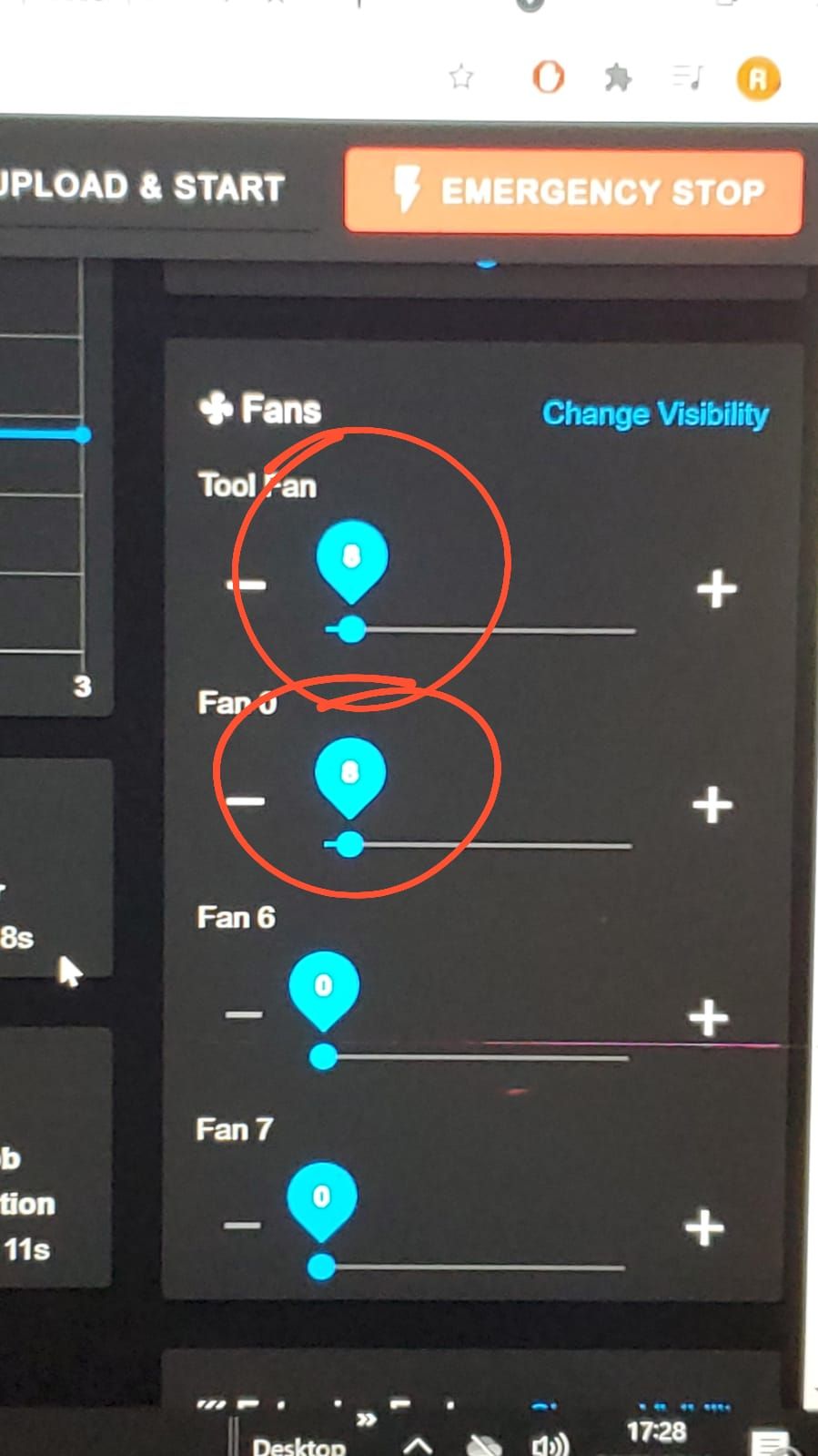
-
Is there any describtion about the wiring for 2 pin fans for toolboard on out1?
thanks
-
; Tools
M563 P0 D0 H1 ; define tool 0Your tool definition is missing an F# to tell it which fan is assigned to that tool.
If it's fan0, add F0.
-
@phaedrux
sadly... it´s still not working
-
Problem solved by using different fan.