Self Leveling (3 motor leadscrew) printer = Non-planar printer?
-
@visionary said in Self Leveling (3 motor leadscrew) printer = Non-planar printer?:
The bed actually rotates around all three axes. Not sure how that is possible with just 3 motors to have "4 axes" (ZABC).
You're right, this is not possible, because those are 4 degrees of freedom and need 4 actuators. In this case Z and rotation by xyz.
In general, there are 6 degrees of freedom: xyz and rotation by xyz, so total 6.
I don't understand your drawing and cannot help you (it's missing information about the 3 dimensions and where the actuators are located. Is the drawing the bed or something else?). One way to solve it: think about the rotations or linear movements of the actuators and what they rotate or move, the effect of motor positions to cartesian coordinates and then back (inverse kinematics).
-
The main triangle's tip's are ball joints moved up and down in Z-direction.
In CAD I can seemingly tilt the bed with combinations of leadscrew movements, but I can't be sure if there is certain position what it can't reach although it might seem that way. The white background picture has minor error in with d4m2 and d4m1.
-
@visionary this looks interesting.
You're using 3 actuators for the bed tilting by changing Z, so according to theory you cannot change 4 degrees of freedom. You can change Z, X rotation and Y rotation by this construction. But you cannot change Z rotation (but you may not need it, because the nozzle direction is not important in most cases).
You should check the sine and cosine rule for non-90 degree angles, whether you can manage to calculate the needed values: https://www.cimt.org.uk/projects/mepres/step-up/sect4/index.htm
If the bed cannot be tilted to every angle (which will be the case), you can restrict those rotations later with parameters and disallowing values outside them.
One point to consider is, that you will probably want the nozze - bed position stay at the same xyz position for printing at an object.
I would do the calculation similar to:
- calculate the blue lines (length and angles change)
- they define a plane (parallel guides and bed being parallel), tilted in 3 dimensions
- calculate change of points*) on the plane by the tilting. This must be corrected by the nozzle xy and z(z by the 3 bed actuators)
*) The plane is in one flat plane (tilted in space, but all 3 edges are in this plane), so the sine/cos functions between blue and white lines are easier to calculate for searching the point.
-
@joergs5 said in Self Leveling (3 motor leadscrew) printer = Non-planar printer?:
@visionary this looks interesting.
You're using 3 actuators for the bed tilting by changing Z, so according to theory you cannot change 4 degrees of freedom. You can change Z, X rotation and Y rotation by this construction. But you cannot change Z rotation (but you may not need it, because the nozzle direction is not important in most cases).
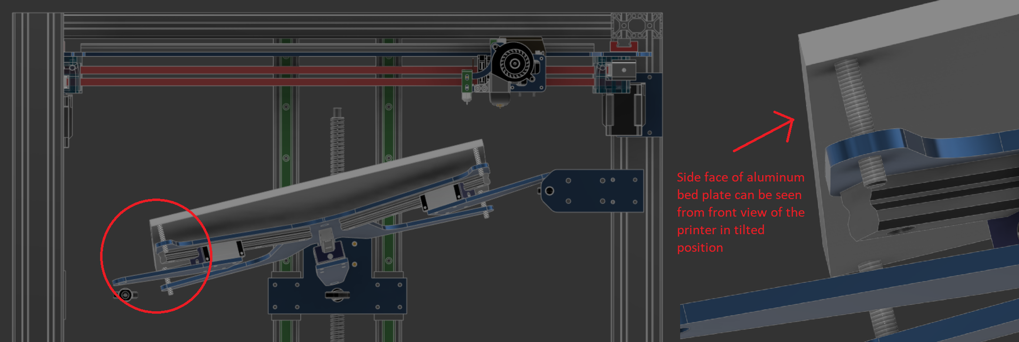
Should side of the bed in following picture be shown? Also see that midpoint of the bed is no longer in the middle of the bed.

I think you're right. I just realized the kinematics don't allow just rotation round Z, but it must anyways be taken into account in calculations.
-
Should side of the bed in following picture be shown?
sorry, please explain what do you mean by "be shown".
With parameter restrictions I meant that some angles will not work because the linear guides are at their limit.see that midpoint of the bed is no longer in the middle of the bed.
Yes, this is what I meant with you'll have to correct xy of the nozzle and Z by lifting up or down all 3 Z motors by the same value when you tilt the bed.
-
This post is deleted! -
@joergs5 said in Self Leveling (3 motor leadscrew) printer = Non-planar printer?:
Should side of the bed in following picture be shown?
sorry, please explain what do you mean by "be shown".
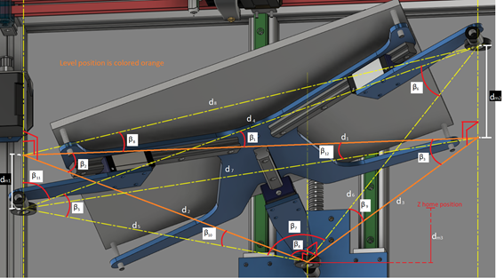
Never mind about that (see picture above). The system is 5 axis.

If I can determine an equation for any of the dimensions shown in red in picture:
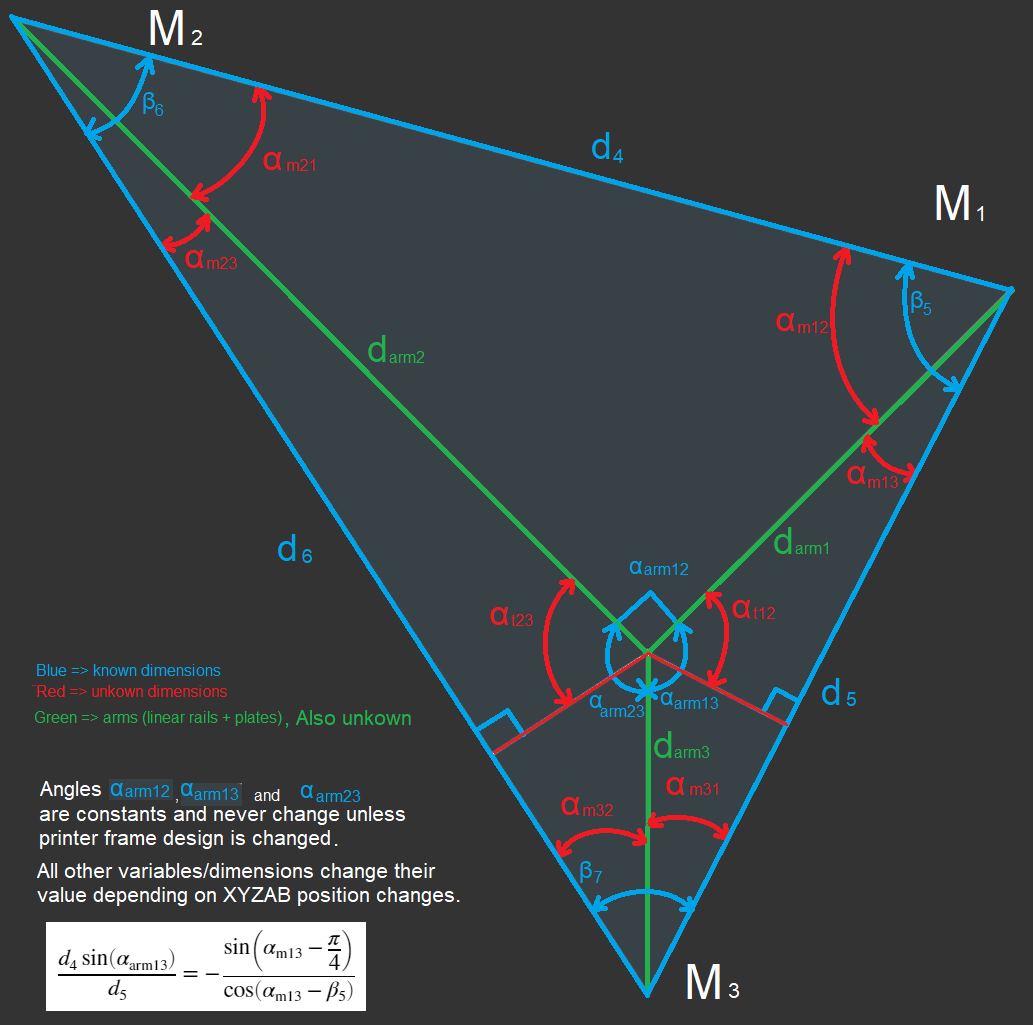
I can determine all the other dimensions easily. I found one solution, but I can't find a way to simplify it to a form alpha_m13 = ...
-
This post is deleted! -
@arnold_r_clark
Nice!
Does your printer work in 5 axes (can do 5 axis Gcode prints?) or is the bed setup for the purpose of automatic true bed leveling?
-
This post is deleted! -
@visionary said in Self Leveling (3 motor leadscrew) printer = Non-planar printer?:
I can determine an equation for any of th
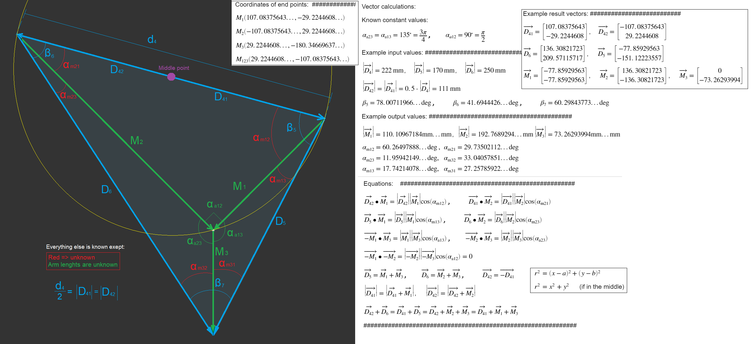
I tried to find a formula, but I had no luck. But my idea so far is:
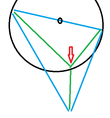
- because of the perpendicularity, the top region defines that the middle point of green lines must be on the circle which has it's center half way of the top line. So it must match a (x – h)^2 + (y – v)^2 = r^2 circle function (x,y being tilted in space).
- right top and right down points are given
- the right green lines have a known angle
So it should be possible (by vector calculation, defining the two right green lines as vectors and a given angle between them, it is some cos function) to calculate the missing angles and green line lengths. The vectors directions are given by the angle between them, starting and end points, and the first vector ends on the circle, and the second starts there.
-
There's no slicers(except a few proprietary ones) that can do anything but basic 2.5d slicing.
Even non-planar slicing hasn't been brought over to slic3r despite it existing for years.The biggest hurdle for any 3d printing in more than 2.5d is the slicer. It's a CS problem that is hard to solve.
-
@roiki11 said in Self Leveling (3 motor leadscrew) printer = Non-planar printer?:
There's no slicers(except a few proprietary ones) that can do anything but basic 2.5d slicing.
When the non-planar kinematics are ready and implemented in RRF, it's time to develop those needed slicers!! The industrial CNC have shown that it is possible.
I have a lot of ideas what can be done with it, starting with finishing 3D printed objects by routing and painting the surface. -
thats honestly the wrong way to go about it. The slicers would need to be developed first, then the hardware. A normal 3D printer can already do non-planar printing. There’s no modifications required(though you would need a special nozzle for optimal performance). for a true 5 axis printing only a simple trunnion with 2 motors is needed. which is trivial to make with a 3d printed parts .
I get it, im more of a hardware guy myself. But this really is putting the cart before the horse(or climbing a tree ass first as we say). We’d need slicer support before any hardware work is really usable. and i dont see any work being done on that front. If i remember the slic3r maintainers were quite hesitant to bring the non-planar slicing work into the mainline slic3r. which is a shame.
-
@roiki11 we should talk about what we mean by non-planar printing, because I think we have a different understanding. If it's just changing the Z while printing in XY, then you're right, and it covers some of the use cases, and mesh compensation is already a non-planar printing (implemented in the controller, as you proposed in another thread). If it includes rotation of the nozzle (or the print bed) and additional actuators are needed, then there are more complex kinematics needed which don't exist in RRF yet.
I expect that noone will develop a slicer for non-planar printing, if there are no printers who can use it (henn egg problem). That's the reason for my approach for a printer first. But I may be wrong. Most users buy printers, so there may never be relative cheap printers with 5 or 6 axes.
A solution might be to start with small additional improvements to slicer and hardware and iterate higher. E. g. starting with code and hardware to print overhangs without support structure and if this works, implementing other use cases.
-
a non-planar printing is simply anything that uses the 3rd axis while printing to create non-planar layers. techically mesh bed compensation falls in to that. kind of. though its not printing non-planar layers.
there is already a fork of slic3r that does non-planar printing. some guy did it as a masters thesis in germany a few years back. People have made machines for 5 axis printing, or a tlting bed printers. Mostly for university work. They just aren’t usable in the real work because there’s no slicer to run them. i don’t see it as a chicken-or-egg problem because the hardware has never been the problem. Making the 5 axis hardware is quite easy. Even the matrix transformations for a 5 axis 3d printer aren’t that complex if you use the BC trunnion method, which mostly comes down to two matrix transformations since no work offset coordinates are needed.Linuxcnc actually has that, has had for years. It’s just not very usable in a machining context and there’s no slicer to try it with a 3d printer.
3D printing didn’t really kick off until a workable slicer emerged. Its the most complex problem to solve.
-
@roiki11 said in Self Leveling (3 motor leadscrew) printer = Non-planar printer?:
Linuxcnc actually has that, has had for years. It’s just not very usable in a machining context and there’s no slicer to try it with a 3d printer.
I'll think about what you wrote.
But I don't understand the sentence above about LinuxCNC. From my understanding, LinuxCNC has G-Code as input, so it's already behind the slicer. This G-Code should be usable by RRF also (maybe some incompatible commands need to be changed by a postprocessor).
-
Linuxcnc is a machine controller, like duet and RRF. The G-code is largely the same, aside from some codes that might be specific to machining or 3D printing. If you had a slicer that would output a 5 axis G-code with the standard tool vector co-ordinates, you could build a 5 axis printer with linuxcnc. Though it’s missing the more advanced 3D printing focused features.
-
Here is better drawing

I'm not yet sure how to solve as I haven't done much match with vectors.
-
This post is deleted!