Bed compensation not working as expected.
-
@donstauffer Run G32 just execute bed.g macro, in this case this file it's empty.
As @CarlosR said, our printer have Z max endstop and a Z probe. When it reach top point endstop after heightmap.csv have been charged, it add some space to the compensation.
In this moment when z=0, all higher points are below the bed surface, but the M114 show the amount of compensation given for that point. -
Someone could give us a hint whats wrong with our setup? We are unable to print if the Z=0 is bellow the bed surface after the heightmap comes into calculation.
-
@marcossf please post config.g bed.g and your homeall.g
-
@pcr Probably our files are a bit complex because we have a lot of variables and complex relations among config files. It's a gantry XY axis, fixed bed, moved by 1XD v1 boards and absolute closed loop encoder motors on all axis Plus 3Z vertical axis with a tool dock each, toolhead type recognition, z lenght switch...
Only the mesh level compensation doen't work as expected as said. At this moment we dont use G32 (bed.g), just issue the commands manually to test it.
- Homeall.g:
T-1 ; unselect tool M584 P5 ; 5 axis visibles G91 ; relative positioning M574 Z2 S1 P"!43.io0.in" M574 U2 S1 P"!44.io0.in" M574 V2 S1 P"!45.io0.in" G1 H1 Z100 U100 V100 F2000 ; lift ZUV relative to current position G1 H1 X-405 Y-255 F2000 ; move quickly to X and Y axis endstops and stop there (first pass) G90 ; absolute positioning M584 P3 ; 3 axis visibles G1 X51 Y0 F2000 ; move to physical X50, Y-61 (logical X0,Y0) M400; G92 X0 Y0 ; establish current position as X0,Y0 G30 K0; z probbing M208 Z0 S1 G1 H4 Z100 F1500 ; lift Z relative to max position M400; set global.noToolMax = {move.axes[2].machinePosition} M208 Z{move.axes[2].machinePosition} S0 M114- bed.g:
M561 ; clear any bed transform G29 S0 ; probe the bed and enable compensation M400 ; wait for movements to finish G28 ; home all- Z-probe config.g part:
;################################# Z PROBE 0 CONFIG #################################
M950 S0 C"out4"                      	    ; create servo pin 0 for solenoid on Out4
M558 P8 C"io3.in" H20 R0.5 F1200 T2000      ; set Z probe type and the dive height + speeds
G31 X0 Y0 Z0                   	    	    ; set Z probe trigger value, offset and trigger height
Maybe we don't understand how the "autolevel" works in RRF. We used before Marlin's autolevel in other machines for years, but the behaviour of this probe and map system seems to act different.
All the compensations of the heightmap.csv are taken in count in all XY coordinates (check with M114) BUT bellow the bed surface once G29 S1 P"heightmap.csv" is loaded. Always it adds 0.70mm of travel to real Z=0 to the compensation given to that point XY.
Our tool leght switch works as expected for each tool, giving a correct Z=0 before activation of the compensation.
-
@marcossf just for refernce If you Machine z Limit in M208 is Z0 it can Not Go any more down. So If your Mesh is negativ it will only Go to Z0 even If the Mesh says EG z -0.8
-
@pcr Being Z=0 after applying the mesh correction, the Z=0 limit calculated is below the bed surface. So it adds more travel to Z axis when mesh is loaded.
Without mesh correction the probe point and the nozzle point Z=0 is correct. We test precision and repetability of Z probe and Z lenght switch and it is consistent, so could be causing innacuracy but both are correct.
Tested with a 3:3 grid, 9:9 grid and 20mm G29 grid gives the same incorrect compensation.
We will try to update to latest beta 3 and look for diferences.
-
Hello again,
We have been trying to reduce the number of variables involved in mesh bed leveling to try to figure out where the problem we are referring (the level of Z = 0 is below the bed surface once the heightmap.csv is loaded).
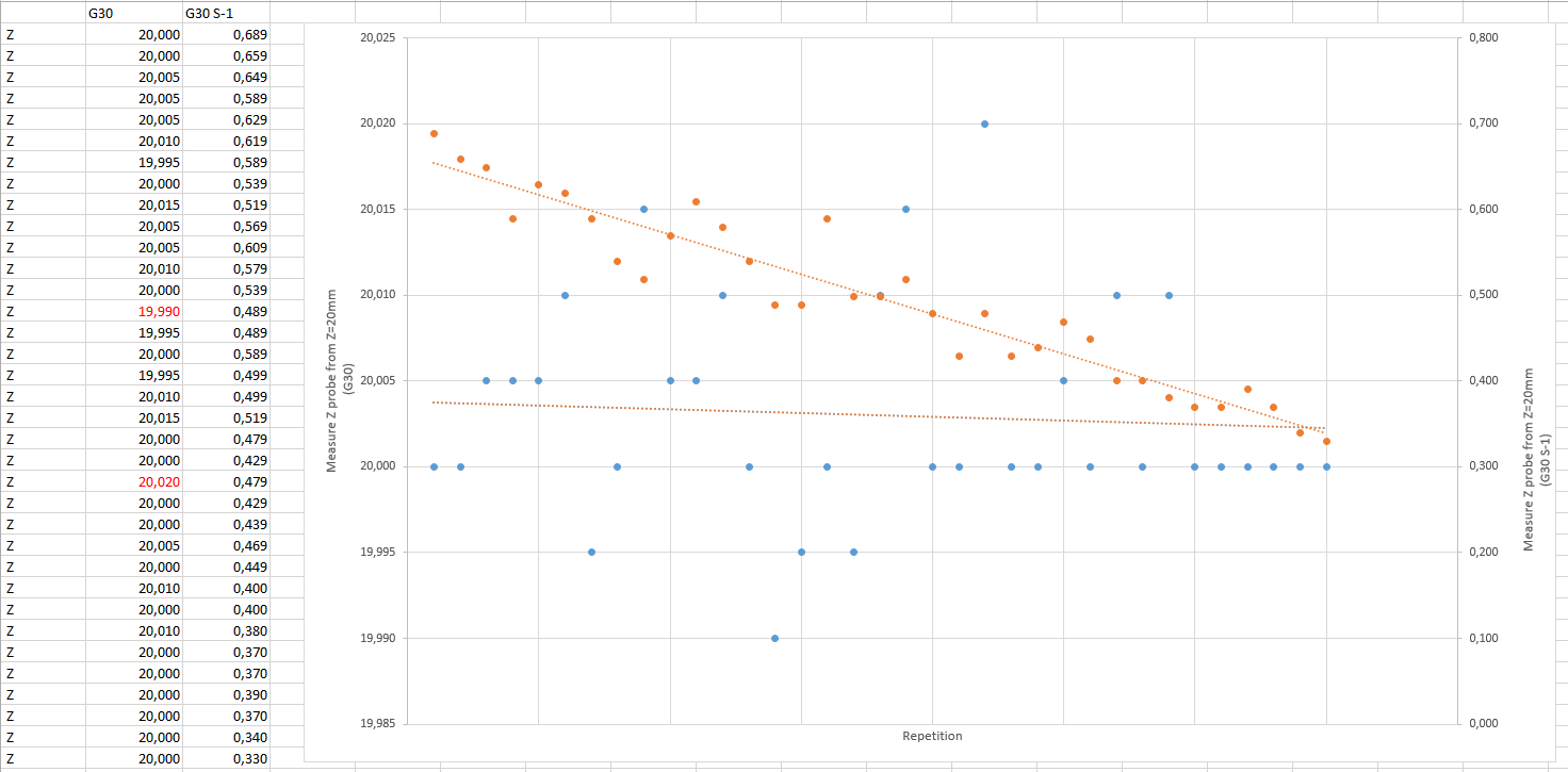
An interesting test was the test of the probe with G30 from 20mm height in X0 Y0 coordinates and the same test where the probe with G30 S-1 triggers from the same height and the same coordinate.
With the G30 we get a reasonably consistent measurement and an average precision of 0.03mm. The problem that we appreciate is if we do the same test with G30 S-1 where it returns the activation height of the probe. What we see is that it increases as we test it.
Could this been the reason for the heightmap being done incorrectly? Why this dissimilar behaviour? We would expect the same linearility than G30 being the same probe and same coordinate.
There isn't any difference with RRF 3.4b2+, 3.4b3 or 3.4b4
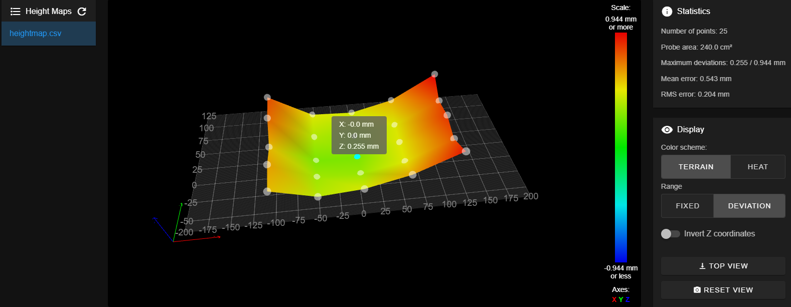
The X0 Y0 in the map is Z 0.255 higher from Z=0 and really is -0.50 below bed surface.
-
@marcossf
Could you try to addG29 S2before each? Could that work (reset the mesh)?I noticed that if not using
G29 S2in start.g file, then z motor stepcount gets lost when repeating measurement withG30->G29. This can be seen by usingM114and comparing the Z stepcount. Maybe observing Z stepcount would be also good to do.Im also trying to solve issues related to
G29and hopefully soon will measure Z axis with encoder.
My earlier theread here Mesh Bed Leveling G29 issues. -
@petriheino Yes, we reset the mesh before the G29 S0.
Also the multiple probe done was with the mesh .csv file erased. It was trying to reduce the parts involved was when discovered the probe measurements deviation. We assume that when make a new map, it is done repeating G30 commands n-times and there is when we see such deviation it can affect the mesh.
Today we'll continue the testing.
-
Hey developers, is there any documentation that could help to troubleshoot mesh? Ive been trying to read the code and understand how to debug mesh, and looked at the Gcode states. Should we concentrate on some of them, where the readings go wrong?
Case 29 (G29)
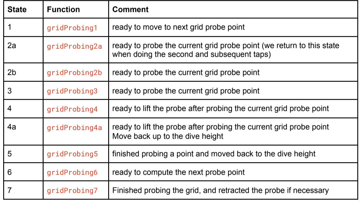
Case 30 (G30)
probingAtPoint0 probingAtPoint1 probingAtPoint2a probingAtPoint2b probingAtPoint3 probingAtPoint4 probingAtPoint4a probingAtPoint5 probingAtPoint6 probingAtPoint7 -
@marcossf said in Bed compensation not working as expected.:
The X0 Y0 in the map is Z 0.255 higher from Z=0 and really is -0.50 below bed surface.
Hi,
Are you aware that if you change the logical Z position (where the firmware "thinks" Z=0 is) before creating the height map the entire height map will appear to move up or down depending on the change?
For example, the command sequences G91 G1 Z0.1 G29 Z0 G90 or G91 G1 Z-0.1 G29 Z0 G90 will shift the logical Z=0 position and a new height map will reflect that shift.
Typically you want the logical Z=0 position to match the physical Z=0 position, so that when you do the command sequence G90 G1 Z0 the nozzle ends up just touching the bed.
-
@fcwilt Interesting. We will check if that situation could been happening with the variables involved in obtain the Z min limit.
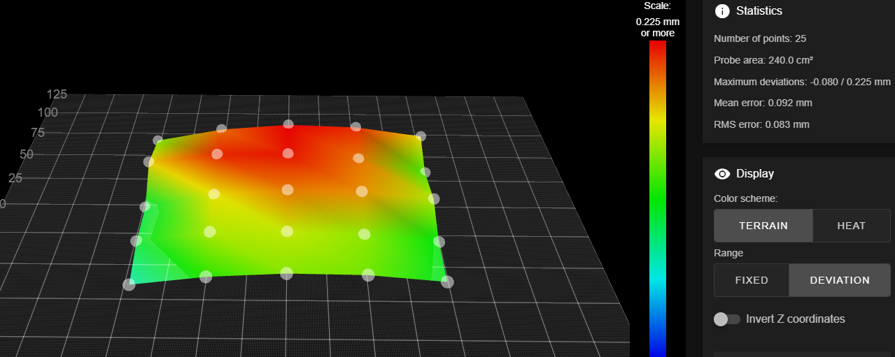
Also we changed the surface for other one that we know it has high and low areas to get more info about this behaviour.
-
To get the best results from your height map you must pick a XY reference point for setting the logical Z=0 position and you must always use that same point when creating and loading the height map.
This process is called setting the Z=0 Datum in the Duet documentation.
Some folks use the XY co-ordinates of one of the grid points used when probing the bed to create the height map.
Others, like me, use the center of the bed.
In either case it should result in a height map in the correct Z relationship with the bed.
Frederick
-
@fcwilt Yes, it's the way we do it. Our HRP when we homing is the bed center (X0 Y0).