Large Format Dowell to Duet conversion
-
@charles-fraser ok and the "general" page?
-
@t3p3tony sorry

-
-
@charles-fraser ok perfect so now satisfied that the right firmware versions are on everything.
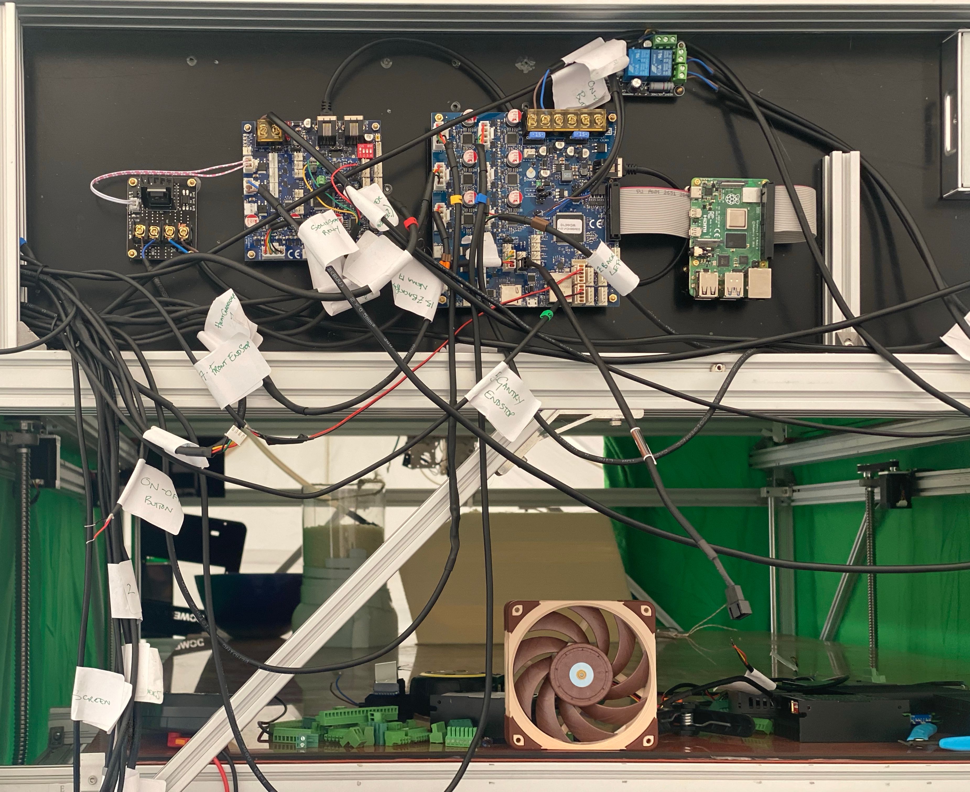
Is this picture still accurate for how the Pi is connected to the Duet?
https://forum.duet3d.com/assets/uploads/files/1631111270670-green-machine-8-9-2021.jpgHow is the PI powered?
-
@t3p3tony nope it now has USB C power

-
@charles-fraser ok so we are now at the point where the SBC is working. The Duet is working. but comms between them don't appear to be working. Please try the following:
-
Power the whole system down and then back up again. In all these changes I am not sure if we have had a full reset.
-
If after #1 DWC does not allow you to send a command to the Duet, connect a USB cable to the Duet's USB port and open up the terminal application you were using and send M122
-
-
Thanks Tony, I did a restart and power off of all systems before but this time I could here the fan spinning on the extruder! Sign of life!
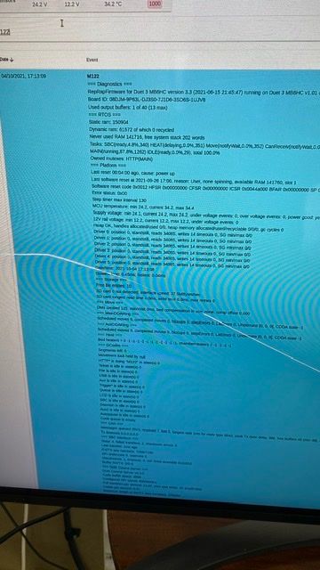
I ran M122 and it printed !! Whoop
-
-
@charles-fraser quick question: to connect to the Pi via USB to “SerialTools about in there” I should use the USB C?
-
@charles-fraser said in Large Format Dowell to Duet conversion:
@charles-fraser quick question: to connect to the Pi via USB to “SerialTools about in there” I should use the USB C?
No the Duet 3 is a micro USB port.
@charles-fraser said in Large Format Dowell to Duet conversion:
I ran M122 and it printed !! Whoop
Ok excellent so now you are at the point where you have communication between the Pi and the Duet MB 6HC, and between the Duet and the 3HC.
Run
M98 P"0:/sys/config.g"That will give you any errors in you config.g that need to be changed.
As an aside,
From now on are you able to send the text of the M122 reports etc using the "</>" function in the forum rather than as an image. It make is easier to see whats going on.
-
I thought you meant connect to the Pi via USB not the Duet
04/10/2021, 17:30:46 M98 P"0:/sys/config.g" CORS disabled CORS disabled CORS disabled -
@t3p3tony okay I have to cycle to the shops to get food before it gets dark and starts raining again. Thank you again for all your help! I will sing duet from the steepletops if we get this working. Also what is your favorite Champagne, Wine and Ale? This Christmas t'wil be flowing!
-
@t3p3tony hi dear Tony, I am taking ladbrokes to court at the moment for bullying tactics and so have spent much of the morning dealing with them and some of my team helping me with things. I’m now able to put a few hours back into the printer if you are around?
I’m happy to pay for your time and or send huge cases of your finest drink to you for christmas if you think you could help me get this printer working?
I posted what was printed after that command in my second to last post. I’m not sure what that response means but I’m trying to get the board to recognise the thermistor and thermocouple with no luck. Please advise. Many thanks, Charles
-
@charles-fraser I think you are now at the point where the boards are working and communicating so the next step is actually setting up and commissioning the printer.
I see from an earlier post that you have gone through and used the config tool to generate the configuration, which we have subsequently modified to remove the non SBC networking stuff. To get rid of the CORS reports when you send M98 P"0:/sys/config.g"
remove the 3 lines starting with M586, then test running M98 P"0:/sys/config.g" again.At that point please post your config.g here using the </> method to make it easy and we can start testing the movement, heaters etc.
-
@t3p3tony Thank you!
-
Okay so all court documents are submitted to the courts in time even though Ladbrookes tried to change the dates on us and then revert back to the old dates last min, and I can get back to work on this:
When I send M98 P"0:/sys/config.g" it just posts that in the event log in a green coloured entry. Nothing else comes back.
Here is the config.g file
; Configuration file for Duet 3 (firmware version 3.3) ; executed by the firmware on start-up ; ; generated by RepRapFirmware Configuration Tool v3.3.3 on Fri Oct 01 2021 16:59:54 GMT+0100 (British Summer Time) ; General preferences G90 ; send absolute coordinates... M83 ; ...but relative extruder moves ; Wait a moment for the CAN expansion boards to start G4 S2 ; Drives M569 P0.0 S1 ; physical drive 0.0 goes forwards M569 P0.1 S1 ; physical drive 0.1 goes forwards M569 P0.2 S1 ; physical drive 0.2 goes forwards M569 P0.3 S1 ; physical drive 0.3 goes forwards M569 P0.4 S1 ; physical drive 0.4 goes forwards M569 P0.5 S1 ; physical drive 0.5 goes forwards M569 P1.0 S1 ; physical drive 1.0 goes forwards M584 X0.0 Y0.1 Z0.2 E0.3:0.4:0.5:1.0 ; set drive mapping M350 X16 Y16 Z16 E16:16:16:16 I1 ; configure microstepping with interpolation M92 X80.00 Y80.00 Z400.00 E420.00:420.00:420.00:420.00 ; set steps per mm M566 X900.00 Y900.00 Z60.00 E120.00:120.00:120.00:120.00 ; set maximum instantaneous speed changes (mm/min) M203 X6000.00 Y6000.00 Z180.00 E1200.00:1200.00:1200.00:1200.00 ; set maximum speeds (mm/min) M201 X500.00 Y500.00 Z20.00 E250.00:250.00:250.00:250.00 ; set accelerations (mm/s^2) M906 X3000 Y3000 Z800 E800:800:800:800 I30 ; set motor currents (mA) and motor idle factor in per cent M84 S30 ; Set idle timeout ; Axis Limits M208 X0 Y0 Z0 S1 ; set axis minima M208 X1200 Y2000 Z1600 S0 ; set axis maxima ; Endstops M574 X1 S1 P"io0.in" ; configure active-high endstop for low end on X via pin io0.in M574 Y1 S1 P"io1.in" ; configure active-high endstop for low end on Y via pin io1.in M574 Z1 S2 ; configure Z-probe endstop for low end on Z ; Z-Probe M558 P9 C"^1.io1.in" H100 F120 T6000 ; set Z probe type to switch and the dive height + speeds G31 P500 X0 Y0 Z2.5 ; set Z probe trigger value, offset and trigger height M556 S50 X0 Y0 Z0 ; set orthogonal axis compensation parameters M557 X15:215 Y15:195 S20 ; define mesh grid ; Heaters M308 S0 P"spi.cs0" Y"thermocouple-max31855" ; configure sensor 0 as thermocouple via CS pin spi.cs1 M950 H0 C"out1" T0 ; create bed heater output on out1 and map it to sensor 0 M307 H0 B1 S1.00 ; enable bang-bang mode for the bed heater and set PWM limit M140 H0 ; map heated bed to heater 0 M143 H0 S80 ; set temperature limit for heater 0 to 80C M308 S1 P"temp0" Y"pt1000" R2200 ; configure sensor 1 as PT1000 on pin temp0 M950 H1 C"out2" T1 ; create nozzle heater output on out2 and map it to sensor 1 M307 H1 B0 S1.00 ; disable bang-bang mode for heater and set PWM limit M143 H1 S300 ; set temperature limit for heater 1 to 300C ; Fans M950 F0 C"out8" Q500 ; create fan 0 on pin out8 and set its frequency M106 P0 S0 H T45 ; set fan 0 value. Thermostatic control is turned on M950 F1 C"out9" Q500 ; create fan 1 on pin out9 and set its frequency M106 P1 S1 H-1 ; set fan 1 value. Thermostatic control is turned off ; Tools M563 P0 S"lily" D0 H1 F0:1 ; define tool 0 G10 P0 X100 Y100 Z0 ; set tool 0 axis offsets G10 P0 R0 S0 ; set initial tool 0 active and standby temperatures to 0C ; Custom settings are not defined -
Dear Tony, I have my k-type thermocouple plugged into 'tc0' on the daughterboard on the expansion board. Is this the correct instruction to set that please?
M308 S0 P"spi.cs0" Y"thermocouple-max31855" ; configure sensor 0 as thermocouple via CS pin spi.cs1Is
M950 H0 C"out1" T0 ; create bed heater output on out1 and map it to sensor 0Mapping out1 on the expansion board? I see no reference to the expansion board?
Is
M308 S1 P"temp0" Y"pt1000" R2200 ; configure sensor 1 as PT1000 on pin temp0Setting the thermistor on 'temp0' on the expansion board? Again I see/understand no reference to the3HC? Same for all heater and sensors for noz and bed - they are all on 3HC and daughter board on the 3HC. Thanks
-
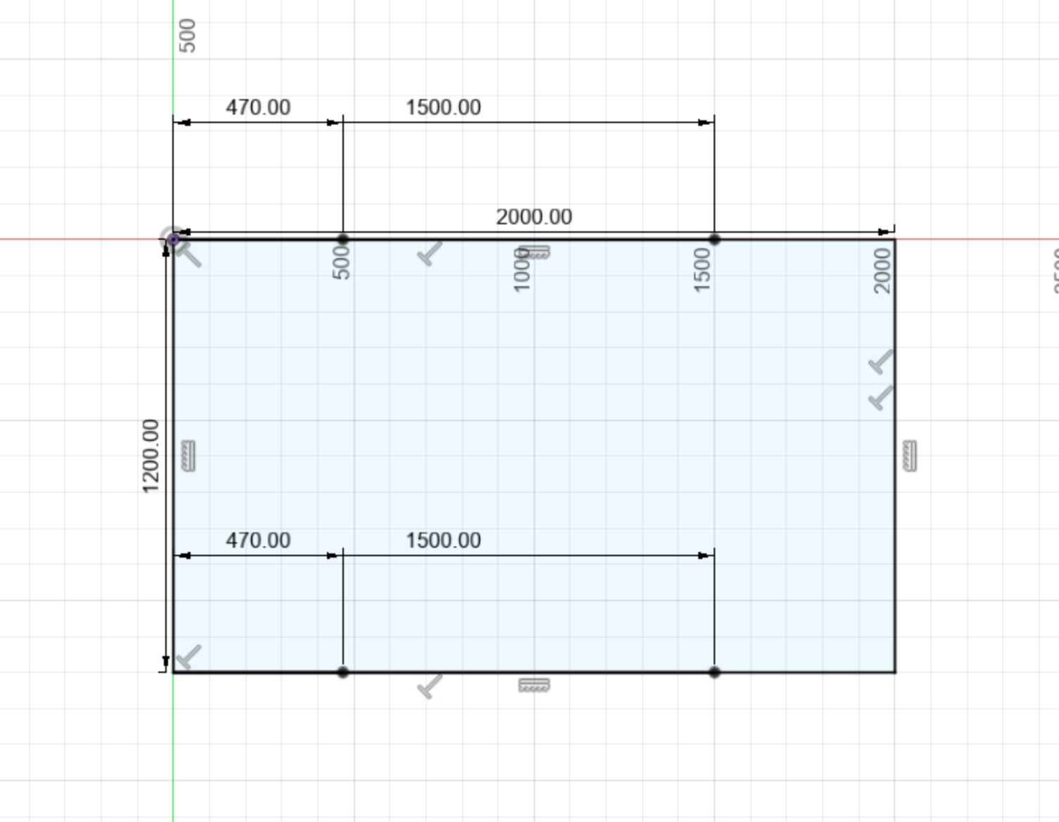
@t3p3tony I also can’t work out for the life of me what the coordinate and drive mapping system is for the 4 x z motors
This is their location measured from X=0 y=0 on the bed looking from above
And here is an up to date mapping of the wires / ports I hope: Green Machine Wiring Table
-
Also the output of the heater for the heated bed goes to a relay. The polarity of the wires seems to matter but I can’t work out which of the pins on ‘OUT0’ on the 3HC is positive or negative. Sorry if this should be possible to determine from the wiring diagram, I still can’t work that out after looking at it


Please NB location of blue and brown wires.
-
@charles-fraser said in Large Format Dowell to Duet conversion:
M98 P"0:/sys/config.g" it just posts that in the event log in a green coloured entry. Nothing else comes back.
Thats good, means there are no commands that are erroring when the machine starts
edited to refer to the table you shared here:
https://docs.google.com/spreadsheets/d/1BnwMvK9tU8W356t2_NAa4YQPk077nXfBA7ScrNfxe_A/edit#gid=0I have only started covering the issues - I can't answer your questions if you ask them quicker than I can answer - 1 step at a time.
I am assuming that the wiring is plugged in as that table refers except the BL touch which is potentially faulty as was preventing the expansion board form starting up. First check there are still no issues with communication or safety after everything is plugged (send M122, M122 B1, check no heaters are heating uncontrollably).
- You have the table showing a Thermocouple being used for the heated bed, connected to thermocouple DB that is plugged into the 3HC. The heater for the heated bed is controlled by a SSR from the 3HC. That should be ok, although the configuration is set to have it connected to the mainboard so lets change that:
M308 S0 P"1.spi.cs0" Y"thermocouple-max31855" ; configure sensor 0 as thermocouple via CS pin 1.spi.cs1 on expansion board 1
M950 H0 C"1.out2" T0                                              ; create bed heater output on expansion board 1 out2 and map it to sensor 0
Cross reference with the 6HC wiring diagram here:
https://duet3d.dozuki.com/Wiki/Duet_3_Mainboard_6HC_Wiring_Diagram
and 3HC wiring diagram here:
https://duet3d.dozuki.com/Wiki/Duet_3_Expansion_3HC_Wiring_Diagram- Similar to point 1, the config does not match your table, change it to:
M308 S1 P"1.temp1" Y"thermistor" T100000  B3800                              ; configure sensor 1 as PT1000 on pin temp0
M950 H1 C"1.out1" T1                                              ; create nozzle heater output on out2 and map it to sensor 1
For some reason you had a PT1000 set in the config, not a thermistor so check that. NOTE the B value in the line above is probably totally wrong as it will be specific to the thermistor. you need to find out what the correct B (and C if the manufacture gives that) values you should be using for this specific thermistor.
-
Fans. Your config has the hotend cooling fan connected to out 8 on the mainboard and the part cooling fan connected to out9. that will be fine if they are both 2 wire fans that run at the same voltage. and fan 1 is your hotend cooling fan, while fan 2 is your part cooling fan.
-
Your table does not match the wiring diagram for motors, You only have 1 Z motor defined and 4 extruders. The table has the following setup:
z back right Driver 3
z front right Driver 2
x Driver 0
y Driver 1
z front left Driver 4
z back left Driver 5
Extruder motor Expansion Driver 0
Note, refer to the mainboard 6HC wiring diagram again - can you confirm that is how you have them plugged in because an earlier image you posted with a schematic had them plugged in differently. Check where each driver is on the mainboard!
The M584 command needs adjusting to correctly assign the driver to the correct axis (assuming the mapping as you have in the table):
M584 X0.0 Y0.1 Z0.2:0.4:0.5:0.3 E1.0This sets the order of the Z motors as Front right, Front left, back left, back right. which is important for Z levelling later.
You also need to adjust the subsequent commands to take into account you have 4 Z motors and 1 extruder.M350 X16 Y16 Z16 E16 I1 ; configure microstepping with interpolation M92 X80.00 Y80.00 Z400.00 E420.00 ; set steps per mm M566 X900.00 Y900.00 Z60.00 E120.00 ; set maximum instantaneous speed changes (mm/min) M203 X6000.00 Y6000.00 Z180.00 E1200.00 ; set maximum speeds (mm/min) M201 X500.00 Y500.00 Z20.00 E250.00 ; set accelerations (mm/s^2) M906 X3000 Y3000 Z800 E800 I30 ; set motor currents (mA) and motor idle factor in per centNote for now I have just removed the additional extruder parameters. The settings there will apply equally to all Z motors which I assume are the same.
- The co ordinates for you motors (for use in M671 later in the process). I think they are as follows based on the image you have posted:
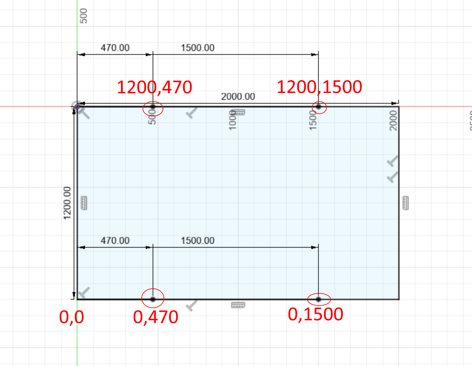
Assuming the motors are where the circles are?
Ok I think that is enough for now. Make the changes to config.g I have suggested and then re-run M98 P"0:/sys/config.g". Then plost config.g here again and we can take the next steps.
