RRF v3.3/Mini 5+ Wifi - Major problems with layer shifting
-
@t3p3tony
Thanks for the answerYes, it's with my normal ASA slicer profile.
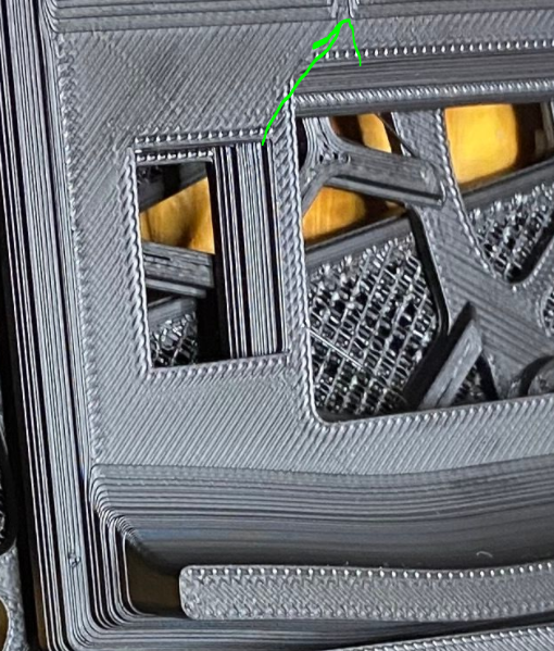
The pictures in the main post shows the layer shifts. I can add some more
I have reprinted these parts more thean five times now so I have a bunch of failures to show.
And I have tried to rearrange tho order of how I apply the mesh, but so far the same result whatever I do.
The problem isn't with small parts in the middle of the bed. The problems seem to be that is scrapes heavily over the larger infill parts of the prints above and I can't understand why.
Usually when I have scraping it's over extrusion or if the bed is wrong the first layer is crap. But here the extrusion factor seems OK and the first layer is great.
-
@t3p3tony
Here is one more picture. Thanks for helping")
In the top part I lowered the extrusion factor to see if that helped. The bottom part is from tonight.

-
@gixxerfast said in RRF v3.3/Mini 5+ Wifi - Major problems with layer shifting:
42STH40-2004MAC
OK. But mostly your Layershifts are due to the current or some loose grub screws.
FYI Klipper Current is RMS RRF is Peak.
so 800ma on klipper is about 1130mA in RRF.
-
@pcr That's very interesting.
I tried to read about that but I must have missed that. So in my config I should have about 1200 mA to match the Klipper 800mA?
I would be very very happy if the solution to the problem is that easy
-
This is in the M906 documentation:

NOTE: As a rule of thumb, the recommendation is to set M906 to use 60-85% of the rated maximum current for the motor.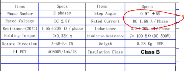
So inbetween 1A and 1.4A then. I'll try that

-
@gixxerfast
Btw, is there somewhere I can see the bed mesh compensation "work". The displayed Z and the one in the object model doesn't show the adjusted Z. Is it possible to see that somewhere?As it's so small adjustments, below .1 mm so it is very hard to notice these by looking (or feeling) at the steppers I guess.
Voron V2.4 (#1317) with Duet 3 Mini5+ Wifi and 1LC v1.1 Toolboard
Voron V0.1 (#637) with Duet 3 Mini 5+ Wifi and 1LC v1.2 Toolboard
Ender 3 Pro with BTT SKR-2 + RRF -
@gixxerfast if you send M122, there is a line that will say 'bed compensation in use: Mesh', or 'none'
If you just was to check it, you can manually edit a couple of the heightmap points so that it will move enough to see
-
@gixxerfast I can feel the lead screws on my z motors moving slightly if mesh compensation is working. Also what does DWC report for mesh compensation?
Looking at the files you shared the print_start.g has a lot going on in it. Potentially interesting are your bed.g (as you run that) and this M98 P"/macros/autoz/autoz.g"
Other thoughts: For the parts where you have the layers squashed as you have shown and the layer shifts, are they still the correct Z height across the whole part?
As there is a lot of different things going on here I would like to simplify things down to the bare minimum. I can propose a couple of tests to help isolate what the issue is
-
create a cube test that recreates the problem so you have a quick print. An example coupld be a 30x30x30 print (not that complicated test print, just a simple cube) placed in one corner of the bed,
-
once you have a quick reproducible issue, try the same print with mesh compensation turned off. You will probably need a with a larger first layer height and ( maybe will not get a not perfect first layer). Don't use your print-start.g at all and edit the start gcode of your test file to remove all references to things that effect bed levelling or mesh compensation.
Depending on how out of level your bed is you will need to be close to the emergency stop if its really out of level. If it is then you may need to run G32 manually before starting the print.
The idea is to see if its mesh bed levelling or something else causing the issues.
-
-
@gixxerfast I understand the Vorons are all CoreXY machines. Are the layer shifts always along one diagonal, the same one each time? If so then it suggests that the motor isn't providing enough torque. Possible reasons include:
- Bad crimp in the cable connecting the motor to the driver
- Motor current accidentally set too low for that driver. Send M906 without parameters during printing, to confirm that the motor currents are correct, and send M913 to confirm that the current is 100% of that value.
- Loose grub screw on motor pulley
- Mechanical issue with that belt/pulley system
- Running the driver in stealthChop mode without executing the proper tuning move during homing. You can use M569 P# D2 to force spreadCycle mode (where # is the driver number), to see if this might be the problem - do this for both XY motors. Note, in stealthChop mode the drive is less able to respond to sudden increases in load, such as when hitting a filament blob or curl-up.
- Bad driver. Try swapping the X and Y motor connections over on the Duet, and swap X and Y in your M584 command. If the problem moves to the other diagonal, it's a bad driver.
Duet WiFi hardware designer and firmware engineer
Please do not ask me for Duet support via PM or email, use the forum
http://www.escher3d.com, https://miscsolutions.wordpress.com -
@gixxerfast so you now have two approaches - looking at the XY motion as @dc42 suggested to ensure that is right, and then looking at Z as I suggested.
I did not think it was XY at first because the layers looked squished in the pictures however it is worth checking to eliminate that as an issue.
-
@t3p3tony
Big, thanks for helping with this problem.I will do as you say and try that.
Given that what's said above about motor current and if with a max motor current of 1.68A that a m906 current of 1.2A is OK, then I'll try that first
The prints are dimensionally accurate in z overall.
The autoz macro is calculation a correction factor between the Z-pin and the bed height and then adjusts the baby-steps.
The value it determines varies by how warm the chamber is and how long it has been warm. The last print it determined the baby step value to -0.08 mm.I can post it later. The bed.g macro is just a standard four point quad gantry leveling.
-
@dc42 said in RRF v3.3/Mini 5+ Wifi - Major problems with layer shifting:
You can use M569 P# D2 to force spreadCycle mode
Thanks DC, I was going to ask about this
I don't want to run in stealthchop anyway.Looking at the failed prints it seems like they shift in a diagonal fashion.
I will up the motor currents, make sure that stealtchchop is disabled and also do the testprints as Tony suggested.
I will have to do that tonight and I will report back the results.
Thanks again all
-
Im really starting to almost give up here.
No matter what I do, I still have layer shifts with this print.

I don't know what to do next. Almost printed a spool of ASA in failed test prints.
What can I do next, any tips please?
I don't want to revert to the old setup as that's a ton of work as I now have a can toolhead board and umbilical instead of cable chains.
- I have recrimped and checked the X motor connector as all layer shifts, shifts to the down(-y)/left(-x)
- Using driver 2 instead of driver 0.
- I have changed the thermistor setting
- Increased printing temperature
- Removed all macro calls (almost) from config.g
- No bed mesh, no auto-z
- Forcing into spreadcycle with a m569 P## D2 for all motors
First layer is good, extrusion is good to OK depending on temp.
Stepper motors are about 60C after print.With Klipper I was running 800/700mA on the A/B-motors and max 5000 mm/s2 acceleration without any problems:
kinematics: corexy
max_velocity: 300
max_accel: 5000    			#Max 4000
#max_accel_to_decel: 3000
##max_accel: 7000    			#Resonance test - remove after test
##max_accel_to_decel: 7000    #Resonance test - remove after test
max_z_velocity: 20 			#Max 15 for 12V TMC Drivers, can increase for 24V
max_z_accel: 350
square_corner_velocity: 5.0
Now I request only 3000 mm/s2 printing acceleration and 5000 transport acceleration. Is this too much for RRF/Duet and my motors, must I lower this?
I printed the 30mm cubes in the corners with mesh and all macros and they printed without problems, but as soon as I try even a single part of the problem print above. I have layer shifts.
The motor harness is a factory crimped harness from Fermio Labs which I've had since I built the printer.
Btw, I use SuperSlicer 2.3.56
2021-10-08 23:58:55	m906
Motor current (mA) - X:1200, Y:1200, Z:1200, E:500, idle factor 70%
2021-10-08 23:56:59 m122 === Diagnostics === RepRapFirmware for Duet 3 Mini 5+ version 3.3 (2021-06-15 21:46:11) running on Duet 3 Mini5plus WiFi (standalone mode) Board ID: H1668-Y296U-D65J0-40KMA-KR03Z-RK6ZH Used output buffers: 3 of 40 (13 max) === RTOS === Static ram: 102724 Dynamic ram: 113872 of which 0 recycled Never used RAM 24252, free system stack 120 words Tasks: NETWORK(ready,40.0%,240) HEAT(delaying,0.1%,344) Move(notifyWait,2.9%,272) CanReceiv(notifyWait,0.1%,773) CanSender(notifyWait,0.1%,357) CanClock(delaying,0.0%,338) TMC(notifyWait,3.3%,72) MAIN(running,50.8%,408) IDLE(ready,0.5%,29) AIN(delaying,2.3%,264), total 100.0% Owned mutexes: WiFi(NETWORK) === Platform === Last reset 02:37:40 ago, cause: software Last software reset at 2021-10-08 21:19, reason: User, GCodes spinning, available RAM 24684, slot 1 Software reset code 0x0003 HFSR 0x00000000 CFSR 0x00000000 ICSR 0x00000000 BFAR 0xe000ed38 SP 0x00000000 Task MAIN Freestk 0 n/a Error status: 0x00 MCU revision 3, ADC conversions started 9457205, completed 9457204, timed out 0, errs 0 Step timer max interval 957 MCU temperature: min 28.6, current 29.9, max 32.8 Supply voltage: min 23.9, current 24.0, max 24.1, under voltage events: 0, over voltage events: 0, power good: yes Heap OK, handles allocated/used 99/8, heap memory allocated/used/recyclable 2048/1308/1206, gc cycles 0 Driver 0: position 81600, standstill, SG min/max 0/0, read errors 0, write errors 1, ifcnt 22, reads 7838, writes 9, timeouts 0, DMA errors 0 Driver 1: position -16000, standstill, SG min/max 0/496, read errors 0, write errors 1, ifcnt 48, reads 7812, writes 35, timeouts 0, DMA errors 0 Driver 2: position 3960, standstill, SG min/max 0/498, read errors 0, write errors 1, ifcnt 45, reads 7812, writes 35, timeouts 0, DMA errors 0 Driver 3: position 0, standstill, SG min/max 0/94, read errors 0, write errors 1, ifcnt 41, reads 7819, writes 28, timeouts 0, DMA errors 0 Driver 4: position 0, standstill, SG min/max 0/76, read errors 0, write errors 1, ifcnt 41, reads 7819, writes 28, timeouts 0, DMA errors 0 Driver 5: position 0, standstill, SG min/max 0/72, read errors 0, write errors 1, ifcnt 41, reads 7819, writes 28, timeouts 0, DMA errors 0 Driver 6: position 0, standstill, SG min/max 0/74, read errors 0, write errors 1, ifcnt 41, reads 7819, writes 28, timeouts 0, DMA errors 0 Date/time: 2021-10-08 23:56:56 Cache data hit count 4294967295 Slowest loop: 224.55ms; fastest: 0.09ms === Storage === Free file entries: 10 SD card 0 detected, interface speed: 22.5MBytes/sec SD card longest read time 4.5ms, write time 1.9ms, max retries 0 === Move === DMs created 83, maxWait 266573ms, bed compensation in use: none, comp offset 0.000 === MainDDARing === Scheduled moves 534220, completed moves 534220, hiccups 0, stepErrors 0, LaErrors 0, Underruns [5711, 58, 8], CDDA state -1 === AuxDDARing === Scheduled moves 0, completed moves 0, hiccups 0, stepErrors 0, LaErrors 0, Underruns [0, 0, 0], CDDA state -1 === Heat === Bed heaters = 0 -1, chamberHeaters = -1 -1 Heater 0 is on, I-accum = 0.4 Heater 1 is on, I-accum = 0.0 === GCodes === Segments left: 0 Movement lock held by null HTTP is idle in state(s) 0 Telnet is idle in state(s) 0 File is idle in state(s) 0 USB is idle in state(s) 0 Aux is idle in state(s) 0 Trigger is idle in state(s) 0 Queue is idle in state(s) 0 LCD is idle in state(s) 0 SBC is idle in state(s) 0 Daemon is idle in state(s) 0 Aux2 is idle in state(s) 0 Autopause is idle in state(s) 0 Code queue is empty. === CAN === Messages queued 549416, received 114039, lost 0, longest wait 2ms for reply type 6049, peak Tx sync delay 438, free buffers 17 (min 3), ts 47301/47300/0 Tx timeouts 0,0,0,0,0,0 === Network === Slowest loop: 205.31ms; fastest: 0.00ms Responder states: HTTP(0) HTTP(0) HTTP(0) HTTP(0) FTP(0) Telnet(0), 0 sessions HTTP sessions: 1 of 8 - WiFi - Network state is active WiFi module is connected to access point Failed messages: pending 0, notready 0, noresp 0 WiFi firmware version 1.26 WiFi MAC address f0:08:d1:02:eb:c9 WiFi Vcc 3.36, reset reason Power up WiFi flash size 2097152, free heap 23880 WiFi IP address 192.168.1.70 WiFi signal strength -50dBm, mode 802.11n, reconnections 0, sleep mode modem Clock register 00002002 Socket states: 0 0 0 0 0 0 0 0; Configuration file for Duet 3 Mini 5+ (firmware version 3.3) ; executed by the firmware on start-up ; ; generated by RepRapFirmware Configuration Tool v3.3.2 on Mon Sep 13 2021 16:36:36 GMT+0200 (centraleuropeisk sommartid) ; Based on configuration by OC-Geek ; General preferences M111 S0 ; Debugging off G21 ; Work in millimetres G90 ; send absolute coordinates... M83 ; ...but relative extruder moves M669 K1 ; select CoreXY mode ; Limit axis M564 S1 H1 ; Forbid axis movements when not homed ; H1 Forbid movement of axes that have not been homed ; S1 Limit movement within axis boundaries ; Wait a moment for the CAN expansion boards to start G4 S2 ; ================================== ; Fysetc 12864 display Color ; ================================== M918 P2 R6 C30 E4 F200000 ; Configure direct-connect display ; P2 128x64 display using ST7567 display driver chip ; R6 Display resistor ratio, in range 1 to 7. Only used with ST7567-based displays. ; The default value of 6 is suitable for the Fysetc Mini 12864 display. ; C30 Display contrast, in range 0 to 100 ; E4 The number of pulses generated by the rotary encoder per detent. Typical values are 2 and 4 ; F... SPI clock frequency in Hz, default 2000000 (i.e. 2MHz) M150 X2 R0 U255 B0 P200 S3 ; Set LED colours ; X2 LED type: X0 (default) = DotStar, X1 = NeoPixel, X2 = Panel 12864 ; R,U,B Set the LED colour (note Fystec uses GRB space instead ... (Red and Green switched over) ; S3 Number of individual LEDs to set to these colours ; ================================== ; NETWORK ; ================================== ; Need to set up WIFI ; M587 S"SSID" P"PWD" ; This needs to be as a first step via USB like when fw ver is checked ; It is permanently stored in the card after that ; https://duet3d.dozuki.com/Guide/1.)+Getting+Connected+to+your+Duet ; Network M550 P"voron2" ; set printer name M552 S1 ; enable network M586 P0 S1 ; enable HTTP (for DWC) M586 P1 S1 ; enable FTP (for remote backups) M586 P2 S0 ; disable Telnet ; ================================== ; DRIVERS ; ================================== ; --- Z Drive map --- ; B_______A ; | 1 | 2 | ; | ----- | ; | 0 | 3 | ; ------- ; front ; ; (looking at the printer from the top) ; Driver directions ; M569: Set motor driver direction, enable polarity and step pulse timing ; This command has LOT of parameters ... e.g. stealthChop2 ... ; Pnnn Motor driver number ; Snnn Direction of movement 0 = backwards, 1 = forwards (default 1) M569 P121.0 S1 D2 ; E - physical drive 121.0 goes forwards M569 P0.2 S1 D2 ; Should be 0, testing with 2 A -> Y - physical drive 0.0 goes forwards M569 P0.1 S1 D2 ; B -> X - physical drive 0.1 goes forwards M569 P0.3 S1 D2 ; Z0 - physical drive 0.3 goes forwards M569 P0.4 S0 D2 ; Z1 - physical drive 0.4 goes backwards M569 P0.5 S1 D2 ; Z2 - physical drive 0.5 goes forwards M569 P0.6 S0 D2 ; Z3 - physical drive 0.6 goes backwards M584 X0.2 Y0.1 Z0.3:0.4:0.5:0.6 E121.0 ; set drive mapping M350 X16 Y16 Z16 E16 I1 ; configure microstepping with interpolation M92 X160.00 Y160.00 Z400.00 E400.00 ; set steps per mm ; Accelerations and speed are set in separate macro M98 P"/macros/set_normal_speed.g" ; Stepper driver currents ; set motor currents (mA) and motor idle factor in per cent ; Drive currents M906 X1200 Y1200 Z1200 E500 I70 ; XYZ and E current M84 S120 ; Idle timeout ; ================================== ; Endstops ; ================================== ; Xn,Yn endstop: 0 = none, 1 = low end, 2 = high end ; Snnn 1 = switch-type (eg microswitch) endstop input ; 2 = Z probe (when used to home an axis other than Z) ; 3 = single motor load detection ; 4 = multiple motor load detection (see Notes) ; P"pin_name" ; Endstops M574 X2 S1 P"^121.io0.in" ; configure active-high endstop for high end on X via pin ^121.io0.in M574 Y2 S1 P"^0.io1.in" ; configure active-high endstop for high end on Y via pin ^io1.in M574 Z0 p"nil" ; No Z endstop ; Extruder never stops :-) ; Axis travel limits ; Mind this is travel NOT print area M208 X0:300 Y0:305 Z-5:265 ; Set axis minima - negative X is to have 0,0 on bed corner ; WARNING on Z not to hit the roof - this is set here ; Belt Locations M671 X-65:-65:365:365 Y0:395:395:0 S20 ; Define Z belts locations (Front_Left, Back_Left, Back_Right, Front_Right) ; Position of the bed leadscrews.. 4 Coordinates ; Snn Maximum correction to apply to each leadscrew in mm (optional, default 1.0) ; S20 - 20 mm spacing M557 X30:270 Y30:270 S40 ; Define bed mesh grid (inductive probe, positions include the Y offset!) ; ================================== ; Bed heater ; ================================== M308 S0 P"temp0" Y"thermistor" T100000 B3950 ; configure sensor 0 as thermistor on pin temp0 M950 H0 C"out0" Q10 T0 ; create bed heater output on out0 and map it to sensor 0 M307 H0 B0 R0.607 C340.7 D1.16 S1.00 V24.1 ;M307 H0 B1 S1.00 ; Enable bang-bang mode for the bed heater and set PWM limit M140 H0 ; map heated bed to heater 0 M143 H0 S120 ; set temperature limit for heater 0 to 120C ; ================================== ; Hotend heater ; ================================== M308 S1 P"121.temp0" Y"thermistor" T100000 B4267 ; configure sensor 1 as thermistor on pin 121.temp0 M950 H1 C"121.out0" T1 ; create nozzle heater output on 121.out0 and map it to sensor 1 M307 H1 B0 R3.391 C160.1:134.1 D4.20 S1.00 V23.8 ;M307 H1 B0 S1.00 ; disable bang-bang mode for heater and set PWM limit M143 H1 S280 ; set temperature limit for heater 1 to 280C ; ================================== ; SENSORS MISC ; ================================== ; Define MCU sensors which will be available in DWC Extra View M308 S3 A"MCU" Y"mcu-temp" ; Officially NOT supported on Mini 3 5+ however seem to work M308 S4 A"Duet Drivers" Y"drivers" ; This is not really working as it is just a threshold crossing ; ================================== ; CHAMBER SENSOR ; ================================== M308 S10 A"Chamber" P"0.temp2" Y"thermistor" T100000 B3950 ; ================================== ; Z PROBES K0 (Klicky mag probe) and K1 (Microswitch Z0) ; ================================== ; M558: Set Z probe type ; P5/P8 select a switch by default (normally closed) for bed probing between the In and Gnd pins of the Z-probe connector ; C specifies the input pin and the optional modulation pin. This parameter is mandatory ; Tnnn Travel speed to and between probe points (mm/min) ; Fnnn Feed rate (i.e. probing speed, mm/min) e.g. 60 is one mm per second ; Hnnn Dive height (mm) ; Annn Maximum number of times to probe each point, default 1 ; Snnn Tolerance when probing multiple times, default 0.03mm ; Rnnn Z probe recovery time before the probing move is started , default zero (seconds) ; B0 B1 Turn off all heaters while probing, default (B0) leaves heaters on. ; I0 Invert (I1) or do not invert (I0, default) the Z probe reading ; G31: Set Current Probe status ; K0 Z Probe Number ; Pnnn Trigger value ; Xnn Ynn Probe offset (from Noozle) ; Znnn Trigger Z height - Set the said Z when the probe triggers !! ; MAG PROBE (GND, IO) ; ----------- ; This is the mag probe with microswitch in Afterburner M558 K0 P8 C"^121.io2.in" T18000 F180 H10 A10 S0.0025 G31 K0 P500 X0 Y20 Z7.612 ; Z-SWITCH ; ----------- ; This is the microswitch which is pressed by the Noozle M558 K1 P8 C"^io5.in" T18000 F180 H3 A10 S0.0025 R0 ; Omron micro switch G31 K1 P500 X0 Y0 Z1.20 ; Part cooling fan M950 F0 C"121.out1" ; create fan 0 on pin 121.out1 and set its frequency M106 P0 S0 H-1 ; set fan 0 value. Thermostatic control is turned off ; Hotend fan M950 F1 C"121.out2" ; create fan 1 on pin 121.out2 and set its frequency M106 P1 S1 H1 T45 ; set fan 1 value. Thermostatic control is turned on ; Controller fan 1 M950 F2 C"out6" ; create fan 2 on pin out5 and set its frequency M106 P2 S1.0 H3:4 T30 C"Controller fan 1" ; controlled by Sensor 3 - MCU ; Controller fan 2 M950 F3 C"out5" ; create fan 3 on pin out6 and set its frequency M106 P3 S1 H0 T45 ; set fan 3 value. Thermostatic control is turned on ; Tools M563 P0 D0 H1 ; define tool 0 G10 P0 X0 Y0 Z0 ; set tool 0 axis offsets G10 P0 R0 S0 ; set initial tool 0 active and standby temperatures to 0C ; Input shaper ;M593 F49 ; Pressure advance ;M572 D0 S0.04 ; Custom settings are not defined ; defines global variables M98 P"/macros/define_global_vars.g" ; Load override parameters M501; Sets normal speeds and acceleration for printing operation M566 X600 Y600 Z60 E8000 ; Set maximum instantaneous speed changes (mm/min) aka Jerk M203 X18000 Y18000 Z3000 E15000 ; Set maximum speeds (mm/min) M201 X5000 Y5000 Z250 E2000 ; Set maximum accelerations (mm/s^2) M204 P3000 T5000 ; Set printing acceleration and travel accelerations; Macro for defining Global variables at start if !exists(global.bed_temp) global bed_temp = heat.heaters[0].active if !exists(global.hotend_temp) global hotend_temp = heat.heaters[1].active if !exists(global.magprobe_status) global magprobe_status = "none" if !exists(global.job_completion) global job_completion = 0 ; output current values echo "global.bed_temp defined. Value : " , global.bed_temp echo "global.hotend_temp defined. Value : " , global.hotend_temp echo "global.magprobe_status defined. Value : " , global.magprobe_status echo "global.job_completion defined. Value : " , global.job_completion; config-override.g file generated in response to M500 at 2021-09-26 01:04 ; This is a system-generated file - do not edit ; Heater model parameters M307 H0 R0.607 C340.700:340.700 D1.16 S1.00 V24.1 B0 I0 M307 H1 R3.391 C160.075:134.066 D4.20 S1.00 V23.8 B0 I0 ; Workplace coordinates G10 L2 P1 X0.00 Y0.00 Z0.00 G10 L2 P2 X0.00 Y0.00 Z0.00 G10 L2 P3 X0.00 Y0.00 Z0.00 G10 L2 P4 X0.00 Y0.00 Z0.00 G10 L2 P5 X0.00 Y0.00 Z0.00 G10 L2 P6 X0.00 Y0.00 Z0.00 G10 L2 P7 X0.00 Y0.00 Z0.00 G10 L2 P8 X0.00 Y0.00 Z0.00 G10 L2 P9 X0.00 Y0.00 Z0.00config (2).g
set_normal_speed.g
define_global_vars.g
config-override.gVoron V2.4 (#1317) with Duet 3 Mini5+ Wifi and 1LC v1.1 Toolboard
Voron V0.1 (#637) with Duet 3 Mini 5+ Wifi and 1LC v1.2 Toolboard
Ender 3 Pro with BTT SKR-2 + RRF -
Btw, this is marked as solved but I can't see any solutions in there. (it's a long thread so I could have missed it)
https://forum.duet3d.com/topic/22436/missing-steps-cant-print-spreadcycle-stealthchop-tuning-help
Seems like I am in the same boat...
-
I got four printers running RRF v3.3 and two of them are using Mini 5+ boards.
Layer shift is not a problem.
So its not a fundamental RRF or Duet problem.
Which leaves us with something about your hardware, your configuration or some of each.
If you post your files using the </> tag it makes it easy for anyone to take a look, as opposed to having to download and open in some editor.
Frederick
-
@fcwilt Hi, yes I don't think there's a general problem with the mini5+
BUT, reading from and talking with quite a few, there's seem to be a problem with 0.9 steppers and the mini5+(TMC2209) / rrf.Do you run 0.9 degrees stepper motors+
-
@gixxerfast said in RRF v3.3/Mini 5+ Wifi - Major problems with layer shifting:
@fcwilt Hi, yes I don't think there's a general problem with the mini5+
BUT, reading from and talking with quite a few, there's seem to be a problem with 0.9 steppers and the mini5+(TMC2209) / rrf.
Do you run 0.9 degrees stepper motors+
No except for one extruder.
Does it appear to be a hardware or firmware compatibility problem with the Mini 5+ and 0.9 steppers?
Frederick
-
@fcwilt I should actually amend my comment. It could be old topics. So I really don't know and shouldn't make such statements.
It's getting late
I might have to edit this a bit tomorrow Cheers
Voron V2.4 (#1317) with Duet 3 Mini5+ Wifi and 1LC v1.1 Toolboard
Voron V0.1 (#637) with Duet 3 Mini 5+ Wifi and 1LC v1.2 Toolboard
Ender 3 Pro with BTT SKR-2 + RRF -
@gixxerfast I get your frustration! especially with those long prints. What we need to work out is what is the root cause of the layer shifts, is it:
a) the print head knocking on the print so there is in issue with Z motion of some sort or
b) the XY motion.Initially I went down the rabbit hole of Z motion due to the mentions of mesh bed levelling being in question, you mentioned the nozzle grinding on the prints, and at least one image looked like squashed layers. I now am not sure about that because of:
@gixxerfast said in RRF v3.3/Mini 5+ Wifi - Major problems with layer shifting:
all layer shifts, shifts to the down(-y)/left(-x)
As you have already pointed out that indicates something with the XY motion, not Z. You have also checked the connector, are confident about the wiring and tried a different driver which eliminates quite a few possibilities also the fact you only see it on the more complex prints makes some causes less likely.
From the look of your new pictures the layer shifts are cumulative, always in the one direction?
I know you have already swapped X from D0 to D2 without resolving the problem. Can you try the following:
Swap the X and Y drivers and motor cables and see if the issue stays the same place or changes to layer shifts in the opposite direction
M584 X0.1 Y0.0 Z0.3:0.4:0.5:0.6 E121.0I have used the driver 0 for the swap here but you can use driver 2 as you currently have it configured if you prefer. The idea is that you change Y and X, not just X.
When/if the layer shifts are happening please do the following:
- Send M906 and M913 with no parameters and confirm that the currents are as expected and at 100%.
- Send M569 P1 and M569 P0 (or P2 if you are using driver 2) and posts the results here.
- Send M122 and post the results here.
-
@t3p3tony said in RRF v3.3/Mini 5+ Wifi - Major problems with layer shifting:
Send M906 and M913 with no parameters and confirm that the currents are as expected and at 100%.
Send M569 P1 and M569 P0 (or P2 if you are using driver 2) and posts the results here.
Send M122Hi, thanks for the reply even on a saturday
I'm in the middle of testing again, but I haven't switched the cables as you suggested just yet as it requires a bit of printer disassembly (quite a bit). I will do it later.
However, I'm starting to wonder if I have beed barking up the wrong tree. With a corexy, if it shifts to -x/-y couldn't that suggest that it's the A-motor (y-motor right one) that is skipping steps when trying to do a non-diagonal move?
Is this something to worry about, btw?
