Duet 2 Wifi Accel Setup
-
question: why is my acccel not found when sending M955 P0 I10.
background: i have hooked up a LIS3DH to a duet 2 wifi. i believe its hooked up correctly per the below link. its hooked up with bread board wire for now though. not sure if thats a problem.
i try to send the following and i get the same type of error in that the board can't be found.
M955 P0 C"spi.cs4+spi.cs3"its possible the accel itself is bad but i am not sure. i know the board is getting 3.3v as i have checked that.
i have not created any config file and not has been created.
-
@cbrunnem2 please show your wiring.
-
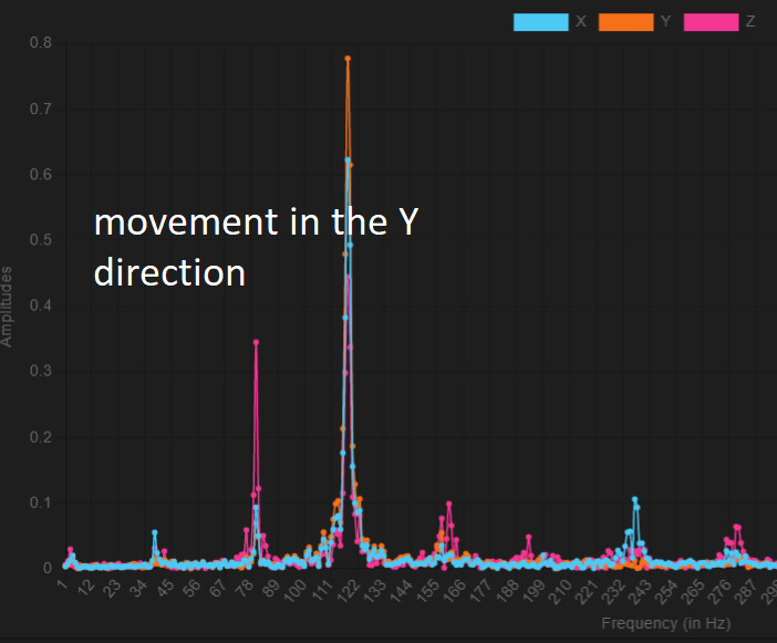
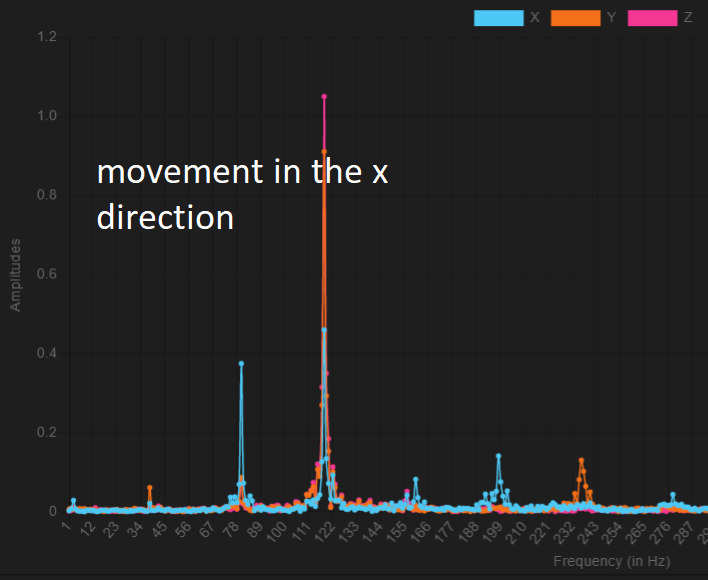
@t3p3tony i was connecting to the paneldue header vs the temp daughterboard header.... im silly. with that being said i did get the following results. based on the FFT of the vibration. it appears i need to add the following to my config.g.
M593 P"zvd" F79
M593 P"zvd" F122although i do suspect that having the dampening on just 40hz would fix this as the other two frequencies 79 and 122 are multiples of 40s
edit: can i confirm this dampening is working by recapturing the data with input shaping turned ON?
-
@cbrunnem2 said in Duet 2 Wifi Accel Setup:
i did get the following results. based on the FFT of the vibration. it appears i need to add the following to my config.g.
M593 P"zvd" F79
M593 P"zvd" F122You can only define one input shaper. the second one will override the first. However, some types of input shaper are effective over a wide frequency range.
although i do suspect that having the dampening on just 40hz would fix this as the other two frequencies 79 and 122 are multiples of 40s
Are you generating that data using the accelerometer plugin, or the input shaping plugin? If you are using the accelerometer plugin, and you are capturing data while the printer is moving, then the 120Hz peak is probably stepper motor noise. The stepper motor noise frequency will change with the movement speed. The input shaper plugin captures data immediately after a move has ended, to avoid capturing stepper motor noise.
edit: can i confirm this dampening is working by recapturing the data with input shaping turned ON?
Yes, if the peaks are showing mechanical vibration, not stepper motor noise. The input shaping plugin has a facility to do that and plot the result on the same graph as the original data with no input shaping.
Duet WiFi hardware designer and firmware engineer
Please do not ask me for Duet support via PM or email, use the forum
http://www.escher3d.com, https://miscsolutions.wordpress.com -
@dc42 i used the command below. I used the accelerometer plugin. i installed the shaping plugin but havent figure that out yet out of lack of need:
G1 X-50 G4 S2 G1 X50 F20000 M400 M956 P0 S1000 A0
for the frequency to input into the accelerometer pluggin, it keeps putting in like 1638 for that but i set 1000 in the command. i assume the S1000 means 1000 samples over 1s. Should i just use the number it auto populates?
when i change the S value to 5000 it changes that value to like 138. i only changed it out of curiosity
-
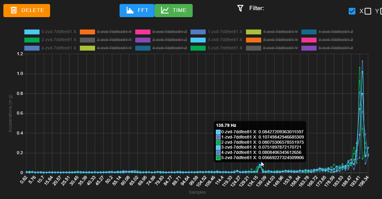
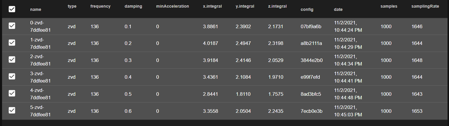
i used the input shaper plugging and tried zvd from .1 to .6 at 136 hz and none made it better. see below
whats interesting is that when i use the plugin, when it moves in hte y axis, it appears to be trying to move at 1000mm/s and the y motor skips a lot of steps. my max speed in firmware is 300mm/s and i know its trying to go faster than that.
also, i know the m953 command is working as when i turn it on and send the below command the travel is super weird if i have the smoothing at .99.
G1 X-50 G4 S2 G1 X50 F20000 M400 M956 P0 S1000 A0
maybe these are just modes i can't get rid of? i do think that a majority of the vibration the accelerometer is seeing is the physical shaking of the whole printer. the printer itself shakes and is not on the best of surfaces so thats a thing. if this algorithm doesnt cancel out that type of movement maybe that could be put into the wiki?