Problem with Mesh Bed Compensation
-
G31 P25 X0 Y-70 Z2.80With your probe offset so far in Y, the droop of the carriage is magnified. Because of the offset, the probe moves up and down with the rotation, while the nozzle, which is under the centre of rotation, moves forward and back. So the bed mesh is valid, but only if the nozzle is where the probe is!
If possible move the probe so it is to the side of the nozzle, with an X offset but no Y offset, rather than in front.
Ian
Bed-slinger - Mini5+ WiFi/1LC | RRP Fisher v1 - D2 WiFi | Polargraph - D2 WiFi | TronXY X5S - 6HC/Roto | CNC router - 6HC | Tractus3D T1250 - D2 Eth
-
Printers: a E3D MS/TC setup and a RatRig Hybrid. Using Duet 3 hardware running 3.4.6
-
@droftarts said in Problem with Mesh Bed Compensation:
the probe moves up and down with the rotation
The rotation of what? I cannot picture what it is.
Frederick
Printers: a E3D MS/TC setup and a RatRig Hybrid. Using Duet 3 hardware running 3.4.6
-
-
Thanks.
I suspect those rods are indeed sagging under the load. The image of the height map you posted is exactly what you would expect to see with that kind of sag.
So you can live with what you have and let mesh compensation deal with it as best it can OR you can redesign your XY gantry to use something more rigid.
Frederick
-
@fcwilt At the moment I cannot change anything, so I would like to use compensation. The problem is that the compensation doesn't seem to work... because on the left side it manages to give me a relatively acceptable height in relation to the plane, while on the right side it doesn't. And I don't understand why.
Tomorrow I will try to modify the map manually, so that I can "force" the compensation only on the right side of the plate.The new deck is being designed, but it requires structural modifications that I cannot install on this one due to lack of space. I will also have to completely redo the Y-axis, which in this way has limitations that I don't like. But we'll talk about that in late spring!
-
Some folks have reported that mesh compensation is not working when it needs to move the probe below Z = 0 if the Z min limit of the bed is 0.
Is that perhaps what you are encountering?
Frederick
-
@fcwilt I had read this and in fact I set
M208 X0:602 Y0:604 Z-3:606
From what I understand, it is as if the compensation has a "limit" beyond which it cannot go.
In the P1 corner, for example, the compensation can correct the Z by more than 0.5 mm. In P3 and P6 this is not the case. I don't understand why and that's what I'd like to know.I don't know if changing the F (Fudge factor) parameter in M671 would improve this... (I still don't understand how it works)...
-
@fcwilt said in Problem with Mesh Bed Compensation:
@droftarts said in Problem with Mesh Bed Compensation:
the probe moves up and down with the rotation
The rotation of what? I cannot picture what it is.
Frederick
I drew you a picture.
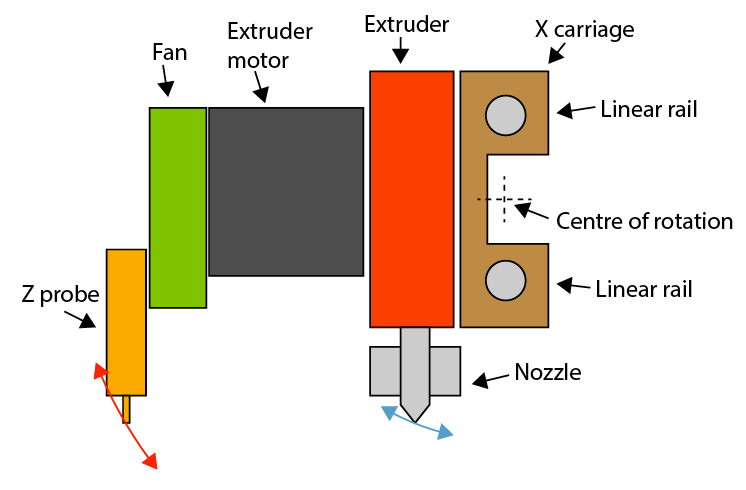
Any sag in the linear rail, and it is usually rotation of the carriage around the X axis, causes a Z probe offset in Y to rotate around the centre of rotation more vertically than the nozzle. The further the probe is offset, the worse the effect. In the above diagram, the Z probe is almost twice the distance from the centre of rotation than the nozzle, so it's an even worse problem, as the error is doubled.This may not be the issue @bernardomattiucci is encountering, as his linear rods are not stacked vertically, but if one linear rod is taking more weight that the other, or is bent, the same effect will be seen.
It's generally better to offset the probe in the X direction, because the probe will have the same rotation around the axis as the nozzle. However, the carriage must not rock, otherwise you get a 'sawtooth' type bed mesh (like the one seen in this thread).
Ian
Bed-slinger - Mini5+ WiFi/1LC | RRP Fisher v1 - D2 WiFi | Polargraph - D2 WiFi | TronXY X5S - 6HC/Roto | CNC router - 6HC | Tractus3D T1250 - D2 Eth
-
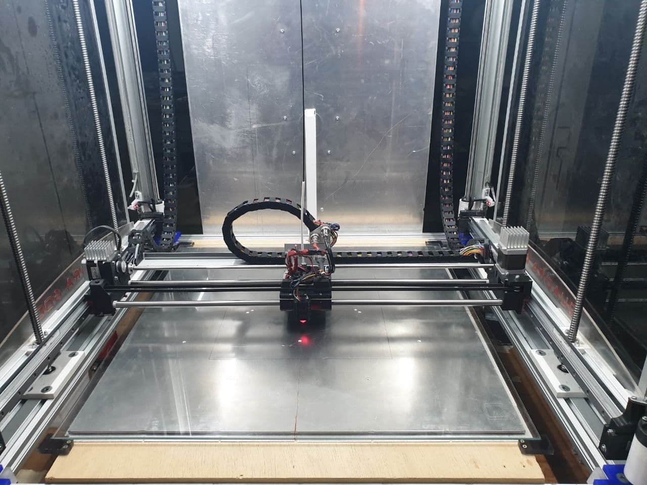
@droftarts This is the head of my printer.
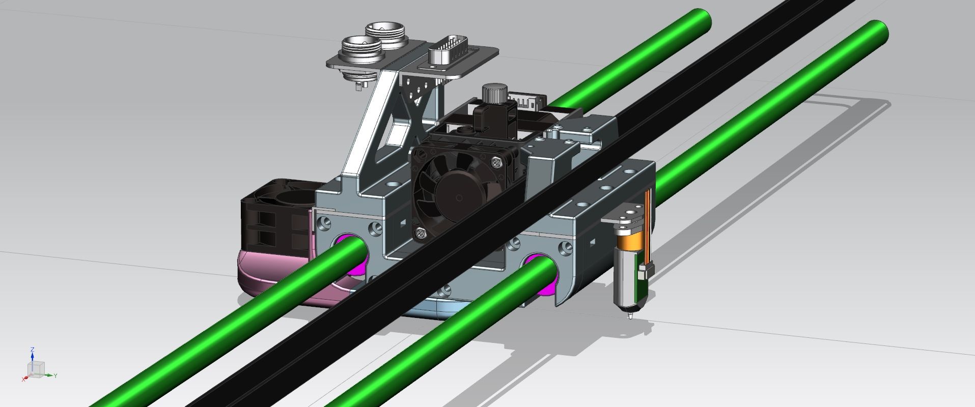
The stand with the connectors is different, as the one in the drawing I can't mount until I complete the printing of the components I need.
There is a little bit of wobble, and in fact I bought a LIS3DH accelerometer to try and find out which component is 'faulty'.
But apart from the oscillations, the problem is not mechanical, but electronic... that is, in the compensation of the mesh, which is carried out regularly and abundantly on the left side (looking at the previous photo) and much, much less on the right side.
-
@bernardomattiucci said in Problem with Mesh Bed Compensation:
that is, in the compensation of the mesh, which is carried out regularly and abundantly on the left side (looking at the previous photo) and much, much less on the right side.
I have not heard of that but it is easy enough to test for.
But that will have to wait until tomorrow.
Frederick
-
One way to narrow down whether the probe tilt is an issue is to set probe type to manual (m558 P0) which allows you do manually touch the nozzle to the bed by jogging to set each point. This can be time consuming for a detailed mesh, but the results would clearly show if the problem is with the probe results or something else.
-
problem solved!
I ran various tests, including making a 5x5 map with m558 p0. The results were not satisfactory and were complex to modify precisely.
So I made, first with BLTouch and then rewrote by hand, a custom 3x3 map, modifying only the values that I was interested in and in the way I wanted to for an acceptable print.The printer in question is a prototype... it is by no means the final version, but I need to print all over the plane and until now I had not had the need to use Mesh Bed Compensation.
Finally I've done it!
-
@bernardomattiucci said in Problem with Mesh Bed Compensation:
Glad to hear you got it working to your satisfaction.
a custom 3x3 map
I guess you know that a denser map is more common. On my printers it ranges from 15x15 to 20x20 points depending on the size of the printable area.
Good luck with your ongoing development.
Frederick
-
@fcwilt Yes, I know that, but at the moment I am not interested in exceptional quality. I just want it to print what I want, how I want it and without too many mistakes.
I will slowly replace the various "definitive" PLA parts with aluminium alloy equivalents, so that all the mechanics become more stable. At that point, having in the meantime replaced the round guides (X and Z with MGN15 recirculating ball bearings), I will be able to create the 20x20 mesh.Thank you
-
It's not perfect but it's still acceptable.
With a 5x5 or denser map, the result would undoubtedly be better, but having built the 3x3 map entirely by hand, with a series of print runs in succession, I can be satisfied. Also because, I repeat, it is a prototype!Test grid: 595x595x0.2 with 1% filling (printed in 32 minutes @25-30mm/s)
-
Good morning and Happy New Year to all,
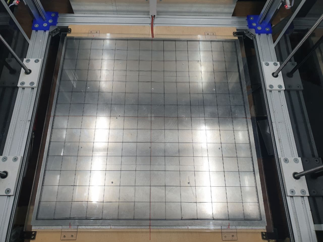
with reference to this post, I wanted to point out that I have solved almost all the problems by completely redoing the print bed support. For some reason it was deforming due to heat, unevenly and this was creating levelling problems.
At the moment I am using an "aluminium tile", of those commonly used for suspended floors, and this has allowed me to solve the problem of mesh compensation.Now I'd just like to insert a "dynamic" control in the mesh.g file (I saw it in one of your files but I don't remember who or where) so as to use a 600x600 mesh when the object to be printed is large, and a 300x300 mesh when the object is smaller. maybe @fcwilt was the author... but I'm not sure.
Could you please help me?