Duet 0.8.5 and Bltouch 3.1
-
I'm trying to revive a pretty old printer with 0.8.5 board. I'm trying to connect Bltouch 3.1 and I'm a bit lost howto wire it and what to do with it then.
I've looked at the wiki but it covers mostly the newer boards and there are plenty of modes available and I can't find the description howto wire things up for each of them - and what to do afterwards (howto set configs).
Can someone help me a tad or point me towards the tutorial that covers the topic?
I've updated the firmware on the machine to 1.21 so far and tried wiring to the PWM 21 pin and probe connector , but while the bloutch powers up it seems I still do something wrong and I have no clue howto go from there. -
@przemas for the BLTouch PWM pin you will need to use one of the expansion heater pins on the expansion connector. You will need to invert the PWM output, which AFAIR in RRF1 and RRF2 is done using the I1 parameter in the M280 command.
Duet WiFi hardware designer and firmware engineer
Please do not ask me for Duet support via PM or email, use the forum
http://www.escher3d.com, https://miscsolutions.wordpress.com -
@dc42 thx - so it seems connecting to pin 21 (heater 3) was a good idea. What about the rest, modes and config? That's the part that got me completely lost.
-
@przemas said in Duet 0.8.5 and Bltouch 3.1:
I've updated the firmware on the machine to 1.21 so far
I'd suggest updating to the most recent firmware available for the older Duets which I believe is 1.26.1
https://github.com/Duet3D/RepRapFirmware/releases/tag/2.05.1
For the config and such you should be able to get a working example using the config tool
https://configtool.reprapfirmware.org/StartBut it should look something like this
; Z-Probe M307 H3 A-1 C-1 D-1 ; disable heater on PWM channel for BLTouch M558 P9 H5 F120 T6000 ; set Z probe type to bltouch and the dive height + speeds G31 P500 X0 Y0 Z2.5 ; set Z probe trigger value, offset and trigger height M557 X15:215 Y15:195 S20 ; define mesh grid -
@phaedrux thank you. Ok, so it uses P mode 9 . In this mode where the probe should get connected (apart from heater 3, pin 21)?This is one of the things that bugs me most and I can't find clear info on it - for example I found some forum posts about mode 4 and connecting to E0.
-
P9 is the dedicated BLtouch mode and is the best way to use it. Though it can be used as a switch but it requires more manual configuration to control the deploy and retract of the pin servo. Using P9 simplifies that.
For the deployprobe.g and retractprobe.g macros they would look like this
; deployprobe.g
; called to deploy a physical Z probe
;
; generated by RepRapFirmware Configuration Tool v3.3.10 on Sat Dec 11 2021 13:29:58 GMT-0600 (Central Standard Time)
M280 P3 S10 I1 ; deploy BLTouch
; retractprobe.g ; called to retract a physical Z probe ; ; generated by RepRapFirmware Configuration Tool v3.3.10 on Sat Dec 11 2021 13:30:36 GMT-0600 (Central Standard Time) M280 P3 S90 I1 ; retract BLTouchIt should be safe to connect the BLTouch black and white wires directly to the ground and IN pins on the Z probe connector. You will need to supply +5V power to the BLTouch, and you will need to connect the BLTouch control input to a PWM-capable output on the expansion connector, (in the examples, heater pin 3 is used)
-
@phaedrux Thank you, you rock. So, I've menaged to get a couple of steps forward with this info. Still failed to make it work. I get:
[ERROR] Error: Z probe already triggered at start of probing moveM401, M402 deploys / retracts the probe correctly.
Here's the config file:; Monkeyfab Prime3D configuration file M111 S0 ; Debug off M550 PPrime3D_50 ; Machine name (can be anything you like) ;M551 Pmonkeyfab ; Machine password (currently not used) ;*** NETWORK SETTINGS M552 P10.0.1.150 ; IP address (0 = use DHCP) M554 P10.0.1.254 ; Gateway M553 P255.255.255.0 ; Netmask M555 P2 ; Set output to look like Marlin M575 P1 B57600 S1 ; Comms parameters for PanelDue ;***GENERAL SETTINGS G21 ; Work in millimetres G90 ; Send absolute coordinates... M83 ; ...but relative extruder moves M574 X1 Y2 Z1 S1 ; set endstop configuration (Y endstop only, at low end, active high) M92 X80 Y80 Z4000 ; Set axis steps/mm M906 X1000 Y1000 Z1000 E1200 ; Set motor currents (mA) ;Axes assignment M569 P0 S0 X0 ; X goes backwards M569 P1 S0 Y0 ; Y goes backwards M569 P2 S0 Z0 ; Z goes backwards M569 P3 S1 E0 ; E0 goes backwards ;***THERMISTORS ;*** If you have a Duet board with 1K thermistor series resistors, change R4700 to R1000 to the following M305 commands M305 P0 T100000 R4700 B4036 H0 L0 ; Put your own H and/or L values here to set the bed thermistor ADC correction M305 P1 T100000 R4700 B4036 H0 L0 ; Put your own H and/or L values here to set the first nozzle thermistor ADC correction M305 P2 T100000 R4700 B4036 H0 L0 ; Put your own H and/or L values here to set the second nozzle thermistor ADC correction ;***HEATERS M307 H0 A128.7 C498 D9.5 B0 ; BED M307 H1 A943.9 C328.4 D8.5 B0 ;M307 H2 A943.9 C328.4 D8.5 B0 M563 P0 D0 H1 ; Define tool 0 G10 P0 S0 R0 ; Set tool 0 operating and standby temperatures ;M106 P0 T45 H1 ;Fan 1 to thermostatic M92 E289 ; Set extruder steps per mm (single nozzle) ;*** If you have a dual-nozzle build, remove or comment out the previous line, and un-comment the following 3 lines ;M563 P1 D1 H2 ; Define tool 1 ;G10 P1 S0 R0 ; Set tool 1 operating and standby temperatures ;M92 E289:289 ; Set extruder steps/mm (dual nozzle) ; Z-Probe M307 H3 A-1 C-1 D-1 ; disable heater on PWM channel for BLTouch M558 P9 H5 F120 T6000 ; set Z probe type to bltouch and the dive height + speeds G31 P500 X0 Y0 Z2.5 ; set Z probe trigger value, offset and trigger height M557 X15:210 Y15:195 S20 ; define mesh grid ;*** if you are using axis compensation, put the figures in the following command M556 S78 X0 Y0 Z0 ; Axis compensation here M201 X3000 Y3000 Z15 E1000 ; Accelerations (mm/s^2) M203 X15000 Y15000 Z100 E3600 ; Maximum speeds (mm/min) M566 X600 Y600 Z30 E20 ; Minimum speeds mm/minute M208 X210 Y210 Z210 ; set axis maxima (adjust to suit your machine) M208 X0 Y0 Z0 S1 ; set axis minimum (adjust to make X=0 the edge of the bed) T0 ; select first hot endhere's homeall:
; Prime3D home all file
; Adjust the bed upper and lower limits in config.g (M208 commands) to get the correct homing positions
G91
G1 X-240 Y240 F3000 S1
G1 X4 Y-4 F600
G1 X-10 Y10 S1
G90
G1 X45 F2000
G91
G90
G1 X45 F2000
G1 Z-240 F400 S1
G1 Z3 F400
G1 Z-8 F200 S1
;G1 X0 Y0 F2000
;G1 Z0
and here's homez:
; homez.g
; called to home the Z axis
;
; generated by RepRapFirmware Configuration Tool v3.3.10 on Tue Dec 14 2021 12:54:21 GMT+0100 (czas środkowoeuropejski standardowy)
G91              ; relative positioning
G1 S2 Z5 F6000   ; lift Z relative to current position
G90              ; absolute positioning
M401
G1 X45 Y45 F6000 ; go to first probe point
G30              ; home Z by probing the bed
M402

; Uncomment the following lines to lift Z after probing
;G91             ; relative positioning
;G1 Z5 F100      ; lift Z relative to current position
;G90             ; absolute positioning
(as you can see I've even tried 401/402 in homez, even though in mode 9 it should work automatically. I've been desperate
 .
.
Here's how the bltouch is connected to z endstop port:
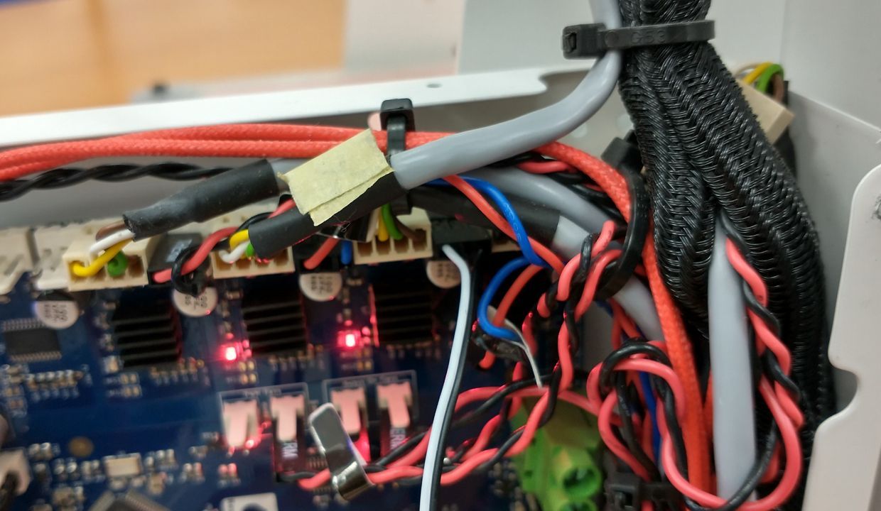
and here's the rest:
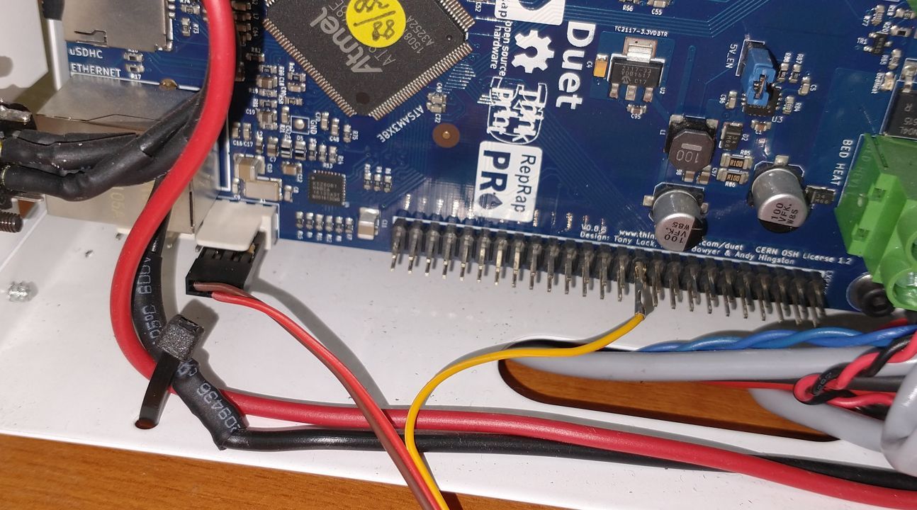
Any suggestions are greatly appreciated, this is the 1st time I'm doing this.
-
nvm, I'm a dumbass. I've left connectinions to a mate and now I see it is all over the place. I've connected it myself and now it works :D.
-
just in case anyone looks for the same thing. I've moved red and brown wire for bltouch from probe pins to pins 2 and 3 on the main pin connector. At same time moved white and black wires to appropriate pins on the probe connector.
-
 undefined Phaedrux marked this topic as a question
-
undefined Phaedrux has marked this topic as solved