No tools are showing in DWC - noob
-
Hello all. I am replacing the board on an old 3D printer with a Duet 2 Wifi and PanelDue 5i. I am very much a noob in regards to coding and working with RRF and DWC. I'm hoping someone here can help me through this. I'm having lots of issues at the moment getting this thing up and running:
- No tools are showing in DWC even though I set them up in the online configurator.
- When homing the Y axis, it only moves about an inch.
- Trying to use the old optical filament runout sensors connected to E0 and E1 endstops but not sure how to setup the config file for them. Since there are no tools showing in DWC nothing regarding the extruder is workingtopconfig.g .
There will be more issues I'm sure, but I'd like to get the #1 solved first.
Steps taken:
Updated all board firmware to current.
Created configuration zip file with online configurator and uploaded via DWC to the system folder.
Refreshed in DWC and on the web browser.
Rebooted machine.
Tried flashing a premade configuration for and Ender 3 just to see if the tools would show up - didn't work.Any help would be greatly appreciated.
Many thanks!
; Configuration file for Duet WiFi (firmware version 3.3) ; executed by the firmware on start-up ; ; generated by RepRapFirmware Configuration Tool v3.3.10 on Sun Jan 02 2022 22:56:18 GMT-0600 (Central Standard Time) ; General preferences M575 P1 S1 B57600 ; enable support for PanelDue G90 ; send absolute coordinates... M83 ; ...but relative extruder moves M550 P"Multoo" ; set printer name ; Network M552 S1 ; enable network M586 P0 S1 ; enable HTTP M586 P1 S0 ; disable FTP M586 P2 S0 ; disable Telnet ; Drives M569 P0 S1 ; physical drive 0 goes forwards M569 P1 S1 ; physical drive 1 goes forwards M569 P2 S1 ; physical drive 2 goes forwards M569 P3 S1 ; physical drive 3 goes forwards M569 P4 S1 ; physical drive 4 goes forwards M584 X0 Y1 Z2 E3:4 ; set drive mapping M350 X16 Y16 Z16 E16:16 I1 ; configure microstepping with interpolation M92 X80.00 Y80.00 Z800.00 E400.00:400.00 ; set steps per mm M566 X900.00 Y900.00 Z60.00 E300.00:300.00 ; set maximum instantaneous speed changes (mm/min) M203 X9000.00 Y9000.00 Z300.00 E2100.00:2100.00 ; set maximum speeds (mm/min) M201 X800.00 Y800.00 Z3000.00 E250.00:250.00 ; set accelerations (mm/s^2) M906 X1300 Y1300 Z1300 E450:450 I10 ; set motor currents (mA) and motor idle factor in per cent M84 S30 ; Set idle timeout ; Axis Limits M208 X0 Y0 Z0 S1 ; set axis minima M208 X480 Y480 Z470 S0 ; set axis maxima ; Endstops M574 X1 S1 P"xstop" ; configure switch-type (e.g. microswitch) endstop for low end on X via pin xstop M574 Y1 S1 P"ystop" ; configure switch-type (e.g. microswitch) endstop for low end on Y via pin ystop M574 Z1 S2 ; configure Z-probe endstop for low end on Z ; Z-Probe M950 S0 C"exp.heater3" ; create servo pin 0 for BLTouch M558 P9 C"^zprobe.in" H5 F120 T6000 ; set Z probe type to bltouch and the dive height + speeds G31 P500 X-32.69 Y-31.88 Z1.5 ; set Z probe trigger value, offset and trigger height M557 X15:215 Y15:195 S20 ; define mesh grid ; Heaters M140 H-1 ; disable heated bed (overrides default heater mapping) M308 S0 P"e0temp" Y"thermistor" T100000 B4725 C7.06e-8 ; configure sensor 0 as thermistor on pin e0temp M950 H0 C"e0heat" T0 ; create nozzle heater output on e0heat and map it to sensor 0 M307 H0 B0 S1.00 ; disable bang-bang mode for heater and set PWM limit M143 H0 S295 ; set temperature limit for heater 0 to 295C M308 S1 P"e1temp" Y"thermistor" T100000 B4725 C7.06e-8 ; configure sensor 1 as thermistor on pin e1temp M950 H1 C"e1heat" T1 ; create nozzle heater output on e1heat and map it to sensor 1 M307 H1 B0 S1.00 ; disable bang-bang mode for heater and set PWM limit M143 H1 S295 ; set temperature limit for heater 1 to 295C ; Fans M950 F0 C"fan0" Q500 ; create fan 0 on pin fan0 and set its frequency M106 P0 S0 H1:2:0 T45 ; set fan 0 value. Thermostatic control is turned on ; Tools M563 P0 S"extruder 0 (model)" D0 H0 F-1 ; define tool 0 G10 P0 X0 Y0 Z0 ; set tool 0 axis offsets G10 P0 R0 S0 ; set initial tool 0 active and standby temperatures to 0C M563 P1 S"extruder 1 (support)" D1 H1 F-1 ; define tool 1 G10 P1 X0 Y0 Z0 ; set tool 1 axis offsets G10 P1 R0 S0 ; set initial tool 1 active and standby temperatures to 0C ; Custom settings are not defined ; Miscellaneous M911 S10 R11 P"M913 X0 Y0 G91 M83 G1 Z3 E-5 F1000" ; set voltage thresholds and actions to run on power loss T0 ; select first tool -
@nvigr8 For the Y axiz, check with M119 to see of the endstop is configured correctly, the slight movement usually means the enstop is already triggered.
For the config.g, use the </> above the messgage box to post it.
-
@stephen6309 Thanks for the reply.
If the Y endstop is already triggered, it would show a red light next to the motor plug on the board correct? That isn't happening when I try to home the Y axis.Apologies, I don't understand what you mean with posting the config.g file. I just edited the post and copy/pasted it in at the bottom.
-
@nvigr8 For the endstop, sending M119 will show the current status. It needs to show triggered only when the switch is depressed. The led will bo one when the switch is closed, but that may not mean it's triggered.
Right above the edit box when posting a message, there is a tool bar, the </> is the 5th one. Hovering over them shows what they do.
-
@stephen6309 Thanks. I tried selecting all the lines from the config.g that I pased and clicking on the icon you mentioned. When I hit submit after, there's an error at the bottom right of the screen saying its read as spam...
-
@nvigr8 When using the </>, click on that first and the location to copy to is already highlighted, all you need to do is ctrl-v.
-
Can you send M122 and M98 P"config.g" in the Gcode console in DWC and post the results?
-
@stephen6309 Thank you for explaining. Got it now.
-
@phaedrux As soon as I get home from work I will do that. Thank you.
-
@stephen6309 I sent M119 and it says the x and y endstops are tripped but nothing is physically touching and activating the switches.
-
@phaedrux This is what M122 shows.
M122
=== Diagnostics ===
RepRapFirmware for Duet 2 WiFi/Ethernet version 3.3 (2021-06-15 21:44:54) running on Duet WiFi 1.02 or later
Board ID: 08DLM-996RU-N85S4-7JKD4-3SJ6R-TA9HR
Used output buffers: 3 of 24 (15 max)
=== RTOS ===
Static ram: 23876
Dynamic ram: 74788 of which 84 recycled
Never used RAM 15668, free system stack 184 words
Tasks: NETWORK(ready,13.6%,237) HEAT(delaying,0.0%,314) Move(notifyWait,0.1%,340) MAIN(running,86.0%,403) IDLE(ready,0.4%,29), total 100.0%
Owned mutexes: WiFi(NETWORK)
=== Platform ===
Last reset 00:04:25 ago, cause: power up
Last software reset at 2022-01-02 22:37, reason: User, GCodes spinning, available RAM 12704, slot 2
Software reset code 0x0003 HFSR 0x00000000 CFSR 0x00000000 ICSR 0x0041f000 BFAR 0xe000ed38 SP 0x00000000 Task MAIN Freestk 0 n/a
Error status: 0x00
Aux0 errors 0,0,0
Step timer max interval 0
MCU temperature: min 17.2, current 25.4, max 25.9
Supply voltage: min 24.0, current 24.2, max 24.4, under voltage events: 0, over voltage events: 0, power good: yes
Heap OK, handles allocated/used 0/0, heap memory allocated/used/recyclable 0/0/0, gc cycles 0
Driver 0: position 0, standstill, SG min/max not available
Driver 1: position 0, standstill, SG min/max not available
Driver 2: position 0, standstill, SG min/max not available
Driver 3: position 0, standstill, SG min/max not available
Driver 4: position 0, standstill, SG min/max not available
Driver 5: position 0
Driver 6: position 0
Driver 7: position 0
Driver 8: position 0
Driver 9: position 0
Driver 10: position 0
Driver 11: position 0
Date/time: 2022-01-04 17:41:18
Cache data hit count 4294967295
Slowest loop: 5.83ms; fastest: 0.17ms
I2C nak errors 0, send timeouts 0, receive timeouts 0, finishTimeouts 0, resets 0
=== Storage ===
Free file entries: 10
SD card 0 detected, interface speed: 20.0MBytes/sec
SD card longest read time 4.2ms, write time 0.0ms, max retries 0
=== Move ===
DMs created 83, maxWait 0ms, bed compensation in use: none, comp offset 0.000
=== MainDDARing ===
Scheduled moves 0, completed moves 0, hiccups 0, stepErrors 0, LaErrors 0, Underruns [0, 0, 0], CDDA state -1
=== AuxDDARing ===
Scheduled moves 0, completed moves 0, hiccups 0, stepErrors 0, LaErrors 0, Underruns [0, 0, 0], CDDA state -1
=== Heat ===
Bed heaters = -1 -1 -1 -1, chamberHeaters = -1 -1 -1 -1
=== GCodes ===
Segments left: 0
Movement lock held by null
HTTP is idle in state(s) 0
Telnet is idle in state(s) 0
File is idle in state(s) 0
USB is idle in state(s) 0
Aux is idle in state(s) 0
Trigger is idle in state(s) 0
Queue is idle in state(s) 0
LCD is idle in state(s) 0
Daemon is idle in state(s) 0
Autopause is idle in state(s) 0
Code queue is empty.
=== Network ===
Slowest loop: 15.85ms; fastest: 0.00ms
Responder states: HTTP(0) HTTP(0) HTTP(0) HTTP(0) FTP(0) Telnet(0), 0 sessions
HTTP sessions: 1 of 8- WiFi -
Network state is active
WiFi module is connected to access point
Failed messages: pending 0, notready 0, noresp 0
WiFi firmware version 1.26
WiFi MAC address f4:cf:a2:6e:86:ef
WiFi Vcc 3.43, reset reason Turned on by main processor
WiFi flash size 4194304, free heap 22208
WiFi IP address 192.168.2.158
WiFi signal strength -66dBm, mode 802.11n, reconnections 0, sleep mode modem
Clock register 00002002
Socket states: 0 0 0 0 0 0 0 0
- WiFi -
-
@phaedrux This is what M98 said
M98 P"config.g"
HTTP is enabled on port 80
FTP is disabled
TELNET is disabled
Error: in file macro line 131 column 38: M563: expected number after 'F'
Error: Tool 0 not found
Error: Tool 0 not found
Error: in file macro line 137 column 40: M563: expected number after 'F'
Error: Tool 1 not found
Error: Tool 1 not found
Warning: Macro file config-override.g not found -
; Tools
M563 P0 S"extruder 0 (model)" D0 H0 F-1 ; define tool 0
G10 P0 X0 Y0 Z0 ; set tool 0 axis offsets
G10 P0 R0 S0 ; set initial tool 0 active and standby temperatures to 0C
M563 P1 S"extruder 1 (support)" D1 H1 F-1 ; define tool 1
G10 P1 X0 Y0 Z0 ; set tool 1 axis offsets
G10 P1 R0 S0 ; set initial tool 1 active and standby temperatures to 0C
Can you try mofifying your tool definition to look like
; Tools
M563 P0 S"extruder0" D0 H0 ; define tool 0
G10 P0 X0 Y0 Z0 ; set tool 0 axis offsets
G10 P0 R0 S0 ; set initial tool 0 active and standby temperatures to 0C
M563 P1 S"extruder1" D1 H1 ; define tool 1
G10 P1 X0 Y0 Z0 ; set tool 1 axis offsets
G10 P1 R0 S0 ; set initial tool 1 active and standby temperatures to 0C
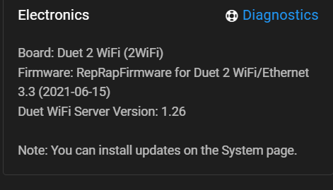
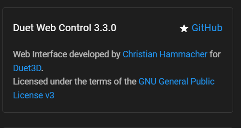
Can you also check the settings tab in DWC and verify the version matches 3.3
-
@phaedrux I didn't see a settings tab but these are from elsewhere in DWC:
-
@phaedrux Ok made the changes to the tool section and now they are showing up in DWC and on the PanelDue. Thank you very much!
However when I touch the heater 1 icon I get : Error Temperature reading fault on heater 1: sensor open circuit
I double checked the wiring and the thermistors are connected to E0 temp and E1 temp.
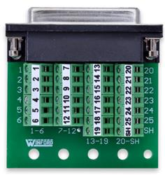
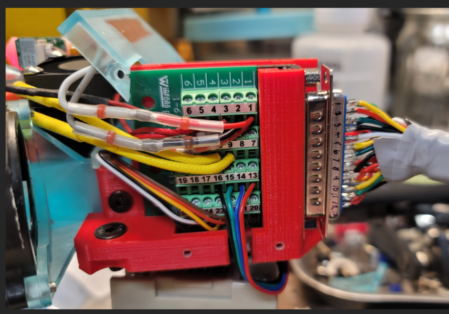
One thing to note and I'm not certain this is an issue, I have a breakout board on the extruder body for all the wiring so that I can just plug one 25pin plug into it to swap out extruders. I've double checked the wiring to make sure everything is going where it should.
Thanks again for your help on this!
-
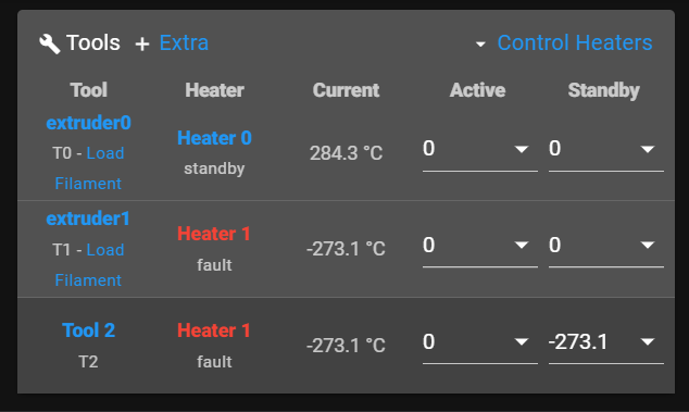
@phaedrux Odd, its now showing two extruders in tool 1 with two heaters and a third heater in tool 2.
-
@nvigr8 said in No tools are showing in DWC - noob:
One thing to note and I'm not certain this is an issue, I have a breakout board on the extruder body for all the wiring so that I can just plug one 25pin plug into it to swap out extruders. I've double checked the wiring to make sure everything is going where it should.
Do you have a wiring diagram for this board?
I would suggest testing the wiring direct to remove the breakout board from the equation. It may be sharing a negative ground connection that the duet uses to switch the heater.
-
@phaedrux To what do I set the active and standby temps? Would you please explain them?
I wired in an extra thermistor directly to the board and did not get the error this time. It reads a normal temp on DWC but on the PanelDue it still reads a crazy number. Also even though I don't have a heated bed in the configuration, it shows one on the Panel Due.
I'll have to draw a diagram for you tonight or tomorrow. I would really like to be able to use this breakout board setup. I have three different extruder assemblies that I will be switching between and it will make the switch so much easier.
Thanks for your help.
-
You probably need to update your paneldue firmware
https://duet3d.dozuki.com/Wiki/PanelDue_Firmware_update
@nvigr8 said in No tools are showing in DWC - noob:
To what do I set the active and standby temps? Would you please explain them?
Normally they would be set by your slicer.
-
@phaedrux This is the breakout board that I'm using:
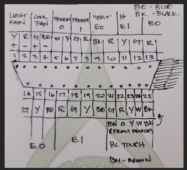
Here is a diagram:
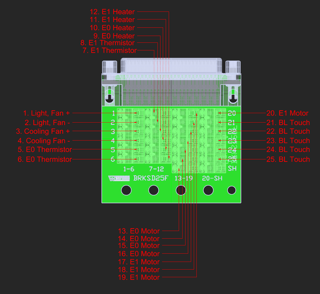
Note: This assembly does not thave E1 and accessories. Connections are there for another two extruder assembly.Here is the corresponding plug pins:
Pic of the whole assembly:
One thing that just occured to me, does soldering thermistor wires cause problems?
Thanks.
