Nema 23 Backlash on direction change
-
@gloomyandy The 80steps/mm are not actually calibrated to the real need of the setup as I am only testing the proper function right now.
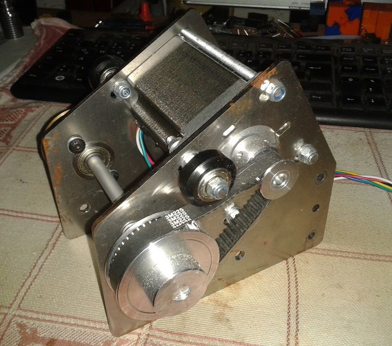
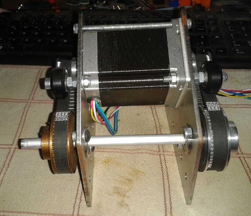
This is my setup

I've had a drive system with a belt and a gear ratio of 3:1 with 2x1,26Nm Nema23 motors which resulted in the same error. I then coupled 2xNema23 1,9Nm motors directly to the axle to isolate the mechanics (thought that maybe the belt stretches too much when changing directions).As you can see in the picture, I've added zip ties around each section where the error could occur to exaggerate the movement of each section (with sections I mean 1)Motor shaft, 2)Coupling, 3)Printer axle, 4)Printer pulley on axle) so I can spot if there would be any mechanical play (I've put some magnets on the shaft of the motor on the back with a zip tie).
If the power of the motors would be to weak, wouldn't they skip steps right away and not be able to rotate the axle at all as the force to overcome the friction should be the highest if we take dynamics out of the equation through slow movement?
-
@semi55 stepper motors might have a lot less slip than a generic electric motor, but they still have some.
It sounds like you are seeing that slip. As the field rotates relative to the rotor, the difference between the two (slip) is what generates the torque. If you are close to the limits of the motor and moving slowly... You can see that slip. Maximum torque it generated at the half step, so basically you are seeing the microsteps being lost in that slip, with the motor catching up as it gets to the half step (or maybe the full step).
The big CNC boys have always said that open-loop steppers are only accurate to the half step for this very reason.
And 2Nm of force needed is quite a lot! -
Here's a link to another microstepping vs torque thread and some text from the Faulhaber site about movement when microstepping.
What Does It Mean? The consequence is that if the load torque plus the motor’s friction and detent torque is greater than the incremental torque of a microstep, successive microsteps will have to be realized until the accumulated torque exceeds the load torque plus the motor’s friction and detent torque. Simply stated, taking a microstep does not mean the motor will actually move. -
@theruttmeister Thanks for your input. So basically stronger motors with less microstepping + maybe going back to a geared solution with a belt would fix the problem or would that make the error only a bit smaller but not 0?
Are closed loop steppers an option to solve this problem otherwise? If so, is it possible to implement them in RRF firmware?
@alankilian Also thanks for your input!
-
@semi55 yes.
Gearing it down with a belt reduction will sacrifice top speed, but might be preferable. From the picture it looks like you have a huge pulley, or is that just for testing?And there are RRF/duet closed loop driver boards, but I have zero experience with them.
There are also multiple options for servo's that can be driven with the step/dir output from the Duet.
-
@theruttmeister Ok, I will try gearing it down then as this is the cheapest possible solution right now. I will post an update if this solves the problem (could take a while due to the upcoming holidays).
Thanks again for your help!
-
@semi55
I made a geared NEMA23 platform using some shapeoko-brackets. They were sold as leadscrew-upgrade parts. Not sure, if they're still available, but it would save you some time. Dual shaft is optional.
BTW: the printed pulley works surprisingly well.


-
@o_lampe Nice setup, thanks for your input.
-
Hi guys,
I have upgraded my system to a 5:1 geared belt driven axis (with 1/8 microstepping) which eliminated the problem with the motor shaft not turning. However, now it seems that the driving belt flexes too much.
I have a genuine Gates GT3 belt in 9mm width which should be sufficient regarding the calculated torque value of around 2Nm if I look at the manufactures datasheet.When I change direction I need 2x0,1mm movements to be able to rotate the axis. I've tried various pretension states of the belt itself without any difference in the result.
Upgrading the belt to an even wider one would probably mean a I have to redesign the whole system as this would require a supporting bearing on the motor shaft.Is it possible to have some sort of backlash compensation software wise?
-
that's allot of "something" you're moving there .
did you consider leadscrews ?
at what voltage are you running the motors?so let me get this straight , just to move your axis you need 2NM , which is close to the rated max holding torque of the motor .
while changing direction the torque needed might be 10 times more , depends on your max speed , accel and jerk setting. -
@hackinistrator thanks for your reply and sry for my delayed answer. Leadscrews aren't an option as I have to stick with the rotating movement instead of linear movement of the axis because it drives another belt.
The motors are running at 24V.
Yes, I need 2Nm roughly to be able to move the axle. I have a gear ratio of 5:1 with 1/8 microsteps and two 1.9Nm Motors which leaves me with 3.7Nm left if 19,51% of the max power of the motor is preserved through 1/8 microstepping regarding the faulhaber website.In theory and in praxis this is enough, the motor is working fine now. Only thing that I've pin pointed is that the timing belt is flexing too much and I am working on a solution for this at the moment.