Duet3D Logo

    Duet3D

    • Register
    • Login
    • Search
    • Categories
    • Tags
    • Documentation
    • Order
    1. Home
    2. alankilian
    • Profile
    • Following 0
    • Followers 3
    • Topics 17
    • Posts 1237
    • Best 340
    • Controversial 1
    • Groups 0

    alankilian

    @alankilian

    Retired firmware/hardware developer.

    416
    Reputation
    101
    Profile views
    1237
    Posts
    3
    Followers
    0
    Following
    Joined Last Online
    Website www.bobodyne.com/web-docs Location Cambridge, MA

    alankilian Unfollow Follow

    Best posts made by alankilian

    • The wide range of DC42's effects.

      I've been helping some artists improve their LED control for "Breathing trees" here in Massachusetts by replacing a string of individually-controlled RGBW LEDs with a simple string of 12 Volt LEDs and a variable-voltage, Arduino-controlled power supply.

      Winterlights- A Circle of Peace inaugural lighting on Dec 4.jpg

      It's working wonderfully and I built them nine controller boards that plug into Arduinos and they are able to change the Arduino code, upload and design breathing patterns by themselves which is an awesome thing for the artists to be able to do.

      They are documenting everything and hoping to teach other artists how to control very dim LEDs without flickering for outdoor/dark use, so I'm sketching a schematic and documenting things.

      I dug around to credit the people who did the original work I copied and guess what????

      The original circuit I used as inspiration was from the good old @dc42 !!!

      So, thanks Dave, your ideas spread far and wide and hopefully will be all the rage in artist/maker spaces in the future.

      I'll add a link in the schematic to your posting so people can reference the original design.

      posted in Off Topic
      alankilian
      alankilian
    • RE: Advice for combined sensor and end stop wiring.

      @exerqtor said in Advice for combined sensor and end stop wiring.:

      @fcwilt

      Nothings carved in stone yet, but why would NC be better?

      If a wire falls off a NC switch or you have an intermittent connection it will trigger early which will stop movement safely.

      If those things happen on a NO switch, it will fail to trigger when homing and you will crash your mechanics.

      If you have electrically-induced noise on the endstop wires caused by stepper motor wires or a heated bed, it <may> cause the endstop to accidentally trigger. NC switches are more immune to that kind of noise.

      posted in Duet Hardware and wiring
      alankilian
      alankilian
    • Very tiny circles using G2 look fantastic.

      I have installed a Duet/Ethernet onto a Rostock Max V3 with an SE300 hotend and I'm trying to print a NASA Saturn V S-IC F-1 combustion chamber by faithfully printing the 356 lower tubes and 178 upper tubes using G2 circles over and over and over and over and over.

      This part has 226,000 G2 commands in it.

      I'm literally amazed that I can print a 1mm diameter circle using a 0.5mm diameter nozzle and it looks great.

      I <almost> can't see the stepper motors turn as it's printing a circle.

      And the extruder also seems to not be moving.

      It's very impressive that the Duet can handle such teensy-tiny movements on a delta printer.

      Thanks for all your work.

      Outside of expansion bell
      Top layer of expansion bell
      Back wall showing small artifact at the layer change

      posted in Example setups and prints
      alankilian
      alankilian
    • I love being able to just print things!

      We couldn't find any double-wide camping cots, so we bought two single-wide ones and I printed some clips to hold them together, and BANG! we had a solution for getting us off the dirt while camping.

      I printed up several 1/4" thick test pieces until I thought I had the design perfect and them did 4 3" long pieces.

      These turned out to be WAY too stiff to clip on, so I did an update making a thinner wall and larger opening, but this design had a wall thickness of 6.7 extrusion widths, so there was an unfilled gap in the center that made them too weak.

      Adjusting the design in CAD reducing the wall thickness by 0.05" and reslicing get me a design with nicely filled-in walls that are the perfect strength to clip on and (barely) able to be removed.

      #iteration

      Thanks Duet team for getting my SeeMeCNC machine off Rambo and onto something I can just design/slice/print and be happy with.

      IMG_6515.jpg
      IMG_6516.jpg
      IMG_6517.jpg

      posted in Tuning and tweaking
      alankilian
      alankilian
    • RE: Duex Controlled Fan Failure

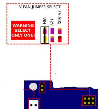
      @jrcl OK, that probably explains it.

      If you have the VFan set to Vin, you'll put either 12 or 24 Volts across your 5 Volt fan depending on what voltage you have on VIN

      Capture.PNG

      posted in Duet Hardware and wiring
      alankilian
      alankilian
    • RE: Ignore One Sensor In Iteration - CNC Start Up Protocol

      @educatingsavvas
      I'm not an expert on the syntax of conditional code, but something like this might work: (Assuming the sensor you want to ignore is 5)

      if sensors.endstops[iterations].triggered && iterations != 5
      

      or, right after the while skip the check for iteration 5:

      if iterations == 5
        continue
      
      posted in CNC
      alankilian
      alankilian
    • RE: Expansion Header Ex_STOP pins

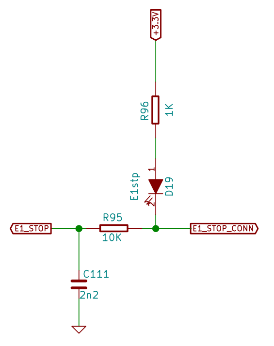
      @Nordle The most compatible way would be to duplicate the input circuitry used for the X, Y and Z_STOP inputs like this:

      Capture.PNG

      Then connect your normally-closed switch between ground and Ex_STOP_CONN in this schematic.

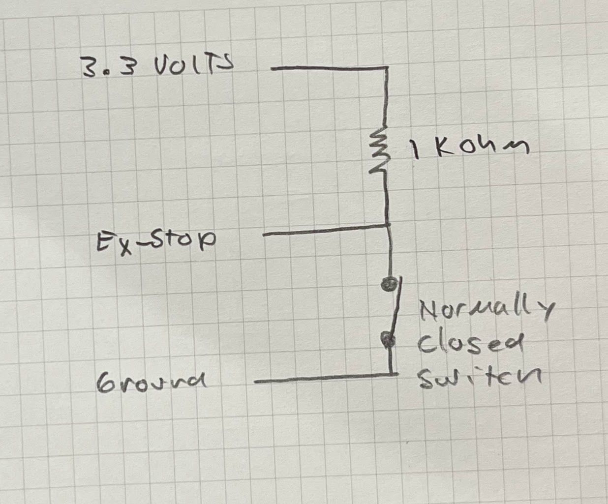
      If you want a more simple input without all the protections and lights, you can try this:
      IMG_8404.jpg

      posted in Duet Hardware and wiring
      alankilian
      alankilian
    • Open-loop for performance, closed-loop for error recovery.

      I'm seeing several groups attempt to make a closed-loop stepper motor controller using encoder feedback and they are all experiencing the same difficulties everyone does implementing a PID control loop.

      • Large errors during speed changes.
      • Unstable oscillation
      • Differing error performance for long and short moves
      • Differing error performance for slow and fast movements

      An idea I've never spent much time on (so it's the BEST idea anyone has thought of yet!) is to NOT do PID/closed-loop control for normal movements and only use it to "close-the-loop" during recovery from errors.

      The idea is that since we all love the performance of our open-loop steppers with microstepping, and we just want to recover from crashed heads or trying to step too fast causing missed steps, just enable closed-loop mode when you detect the error between actual and commanded position is larger than a setpoint.

      When switching in and out of closed-loop mode you'll get blobs and errors in your print, but you had those anyway due to the missed steps that triggered the mode change in the first place.

      This method would still require some motor/mechanical-system analysis and tuning, but would not come into play except when there already was an error on printing, and would only be in effect for a short time during the correction of errors phase so it would have much less change of causing catastrophic errors in position compared to a full-time PID loop running.

      Anyway, it's an idea and I thought I should bring it up to the team implementing the closed-loop control stuff.

      If it's a terrible idea I can live with that. I've had many. 🙂

      posted in Hardware dev
      alankilian
      alankilian
    • RE: Correct way to power 1LC?

      @Reine Out0 is normally used for a high-current bed heater.

      The reason it's listed as an input and an output is that YOU get to select and provide the correct voltage for your bed and it can be different than the voltage used to power the Duet.

      So, you "input" voltage on one pair of terminals and you "output" voltage on the other pair of terminals that connect to the bed heater.

      Out0 is called a "switched-ground" output rather than a "switched power" output, so you cannot use it to power your 1LC.

      You can read a LOT more in the Duet wiring documentation.
      THIS links to the Duet3 6HC bed heater part.

      (OK, it might just barely be possible to power a 1LC from out0, but there's a lot of things to consider re: grounds, and since you're asking, I think you're slightly less experienced than an expert, and you could get into a lot of confusing issues if you don't completely understand everything.)

      So, power your 1LC by applying between 12 and 32 Volts to the power connector and you'll be cool.

      posted in Duet Hardware and wiring
      alankilian
      alankilian
    • RE: NC Microswitch Z Probe with 3.2.2

      @MakeStuffMakeStuff said in NC Microswitch Z Probe with 3.2.2:

      what does the pull up resistor do

      You have a switch connected from ground to an input pin on the CPU.

      The CPU reads the voltage at the pin.

      • If it's above a certain level, it returns a binary one.
      • If it's below a certain value, it returns a binary zero.

      When your switch is closed, it's connecting the pin to ground, and when the CPU reads the voltage at the pin, it's pretty close to zero and it returns a binary zero.

      When your switch is open, the pin is not connected to anything, and is just floating around. Sometimes, the CPU will read a low voltage and STILL return a binary zero.

      The "pull-up" resistor is a high-value resistor that connects to a positive voltage, so when your switch is open, it "pulls-up" the pin to a higher voltage and the CPU reads it as a high-enough voltage to return a binary one.

      When your switch is closed, the resistor still tries to "pull" the pin up to a higher voltage, but the resistor's value is too large to do that and your switch wins the fight and can drive the voltage at the pin close to zero.

      posted in General Discussion
      alankilian
      alankilian

    Latest posts made by alankilian

    • RE: Using close loop Encoder for Nema 23

      @JlunaMX Yes, you need to attach a magnet to the stepper motor and mount the boards on the back of the stepper motors with the correct spacing.

      THIS DOCUMENT talks about how to attach the magnet to the back of the stepper motor.

      posted in Third-party add-ons
      alankilian
      alankilian
    • RE: Help with Closed Loop HSS57 Driver and Duet3

      @FLSMichael OK, sorry about that.

      It looks like you need to buy an HISU Adjuster to change the parameters.

      It's good to look at everything you need to use before deciding on a motor driver.

      posted in Duet Hardware and wiring
      alankilian
      alankilian
    • RE: Help with Closed Loop HSS57 Driver and Duet3

      @FLSMichael This YOUTUBE VIDEO should get you everything you need to talk to the motor driver.

      posted in Duet Hardware and wiring
      alankilian
      alankilian
    • RE: BLTouch passes self test, will not manually deploy.

      @Design THIS LINK should help you get it working.

      posted in Duet Hardware and wiring
      alankilian
      alankilian
    • RE: Replace HS557 with 1HCL

      @Lexan

      • Why do you need a closed-loop motion control system on a 3D printer?
      • What aspect of your motion-control system do you want to get out of a closed-loop system that an open-loop system cannot deliver?
      posted in General Discussion
      alankilian
      alankilian
    • RE: Help with Closed Loop HSS57 Driver and Duet3

      @FLSMichael

      I couldn't find ANY manual that describes SIX blinks on the LED. Are you sure they both blink SIX times?

      Do both drivers blink when the print fails?

      What do you have the position error limit (register P16) set to on the drive?
      While you're at it, what do you have the gain registers P1 through P9 set to?

      posted in Duet Hardware and wiring
      alankilian
      alankilian
    • RE: Correct way to power 1LC?

      @jay_s_uk said in Correct way to power 1LC?:

      The 3HC v1.02 and 6HC v1.02 can accept up to 48v as an input voltage

      HEY!!! Look at that.

      I usually google, get to the obsolete documentation which has a link to the new documentation and sometimes that's still old.

      This is good to know, thanks.

      posted in Duet Hardware and wiring
      alankilian
      alankilian
    • RE: Correct way to power 1LC?

      @Reine said in Correct way to power 1LC?:

      So with the v1.02 I could run steppers at 48v and power the bed from the Duet at 24v? That's neat!

      OUT0 has its own power supply input and it can be a different voltage than the rest of the board.

      • I don't think anything runs at 48 Volts though. +32 is the max as far as the documentation says.
      posted in Duet Hardware and wiring
      alankilian
      alankilian
    • RE: Correct way to power 1LC?

      @Reine Out0 is normally used for a high-current bed heater.

      The reason it's listed as an input and an output is that YOU get to select and provide the correct voltage for your bed and it can be different than the voltage used to power the Duet.

      So, you "input" voltage on one pair of terminals and you "output" voltage on the other pair of terminals that connect to the bed heater.

      Out0 is called a "switched-ground" output rather than a "switched power" output, so you cannot use it to power your 1LC.

      You can read a LOT more in the Duet wiring documentation.
      THIS links to the Duet3 6HC bed heater part.

      (OK, it might just barely be possible to power a 1LC from out0, but there's a lot of things to consider re: grounds, and since you're asking, I think you're slightly less experienced than an expert, and you could get into a lot of confusing issues if you don't completely understand everything.)

      So, power your 1LC by applying between 12 and 32 Volts to the power connector and you'll be cool.

      posted in Duet Hardware and wiring
      alankilian
      alankilian
    • RE: Duet 2 Wifi and Geckodrive G320x on Stepper Channels 10 and 11

      @sebkritikel said in Duet 2 Wifi and Geckodrive G320x on Stepper Channels 10 and 11:

      No luck with a 'full' config.g with the BLDC mapped to 'E'.

      I'm both happy you got motion and sad I can't help you with your remaining problem.

      I do want to say that you do not have a BLDC motor, you have a Brushed DC motor if you are indeed using the Gecko drive you referenced earlier.

      TERMINAL 3 Armature (-) Connect the black lead of your motor to this terminal.
      TERMINAL 4 Armature (+) Connect the red lead of your motor to this terminal.
      
      posted in Duet Hardware and wiring
      alankilian
      alankilian