Heaters will not turn on
-
@dc42 please find below the output for M950 and M307 commands
M950 H0
Heater 0 pin out0 frequency 250Hz, sensor 0
M307 H0 Heater 0 model: heating rate 0.593, cooling time constant 389.7, dead time 3.93, max PWM 1.00, calibration voltage 0.0, mode PID Computed PID parameters: setpoint change: P76.6, I1.957, D210.7, load change: P76.6, I5.418, D210.7M950 H1 Heater 1 pin out1 frequency 250Hz, sensor 1M307 H1 Heater 1 model: heating rate 1.680, cooling time constant 233.0/193.0, dead time 6.75, max PWM 1.00, calibration voltage 23.7, mode PID Computed PID parameters: setpoint change: P15.7, I0.397, D74.4, load change: P15.7, I0.865, D74.4The PID parameters are the same as in my config.g for H0 and H1.
Below is output for M98
M98 P"config.g" HTTP is enabled on port 80 FTP is disabled TELNET is disabled -
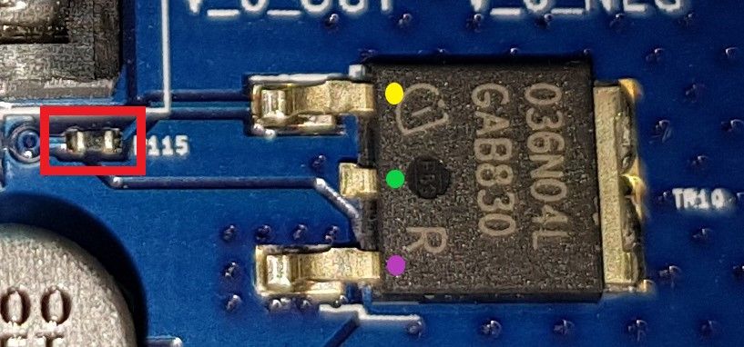
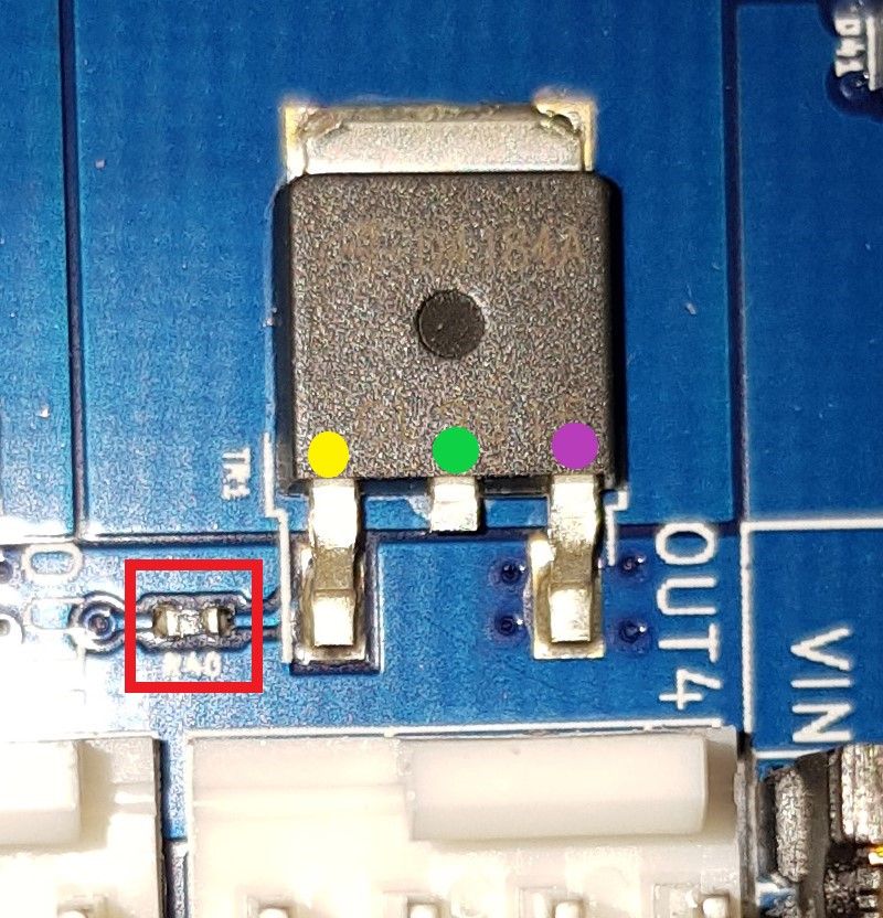
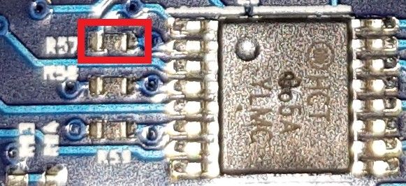
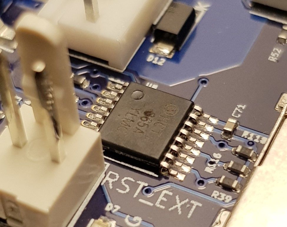
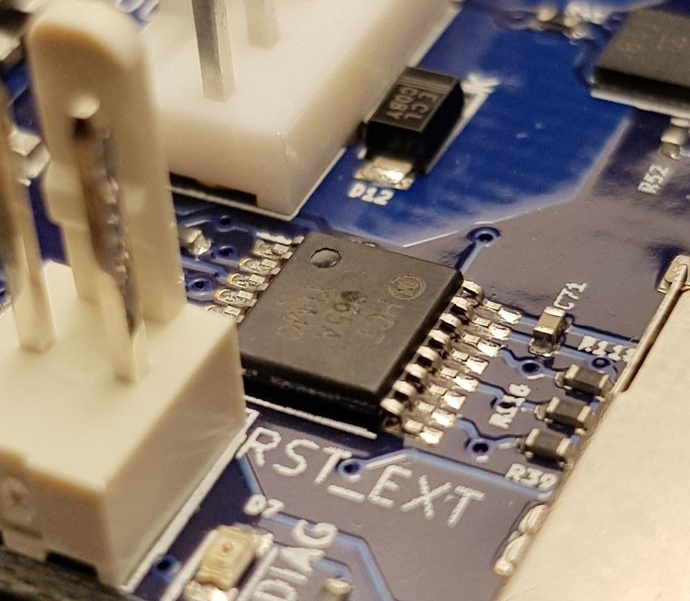
@dc42 please find below pictures for R115, R40 and R57. Is R53 located next to temp3 pin by chance?
I have put 3 coloured dots on the mosfet pins for R115 and R40, if you do not mind could you please tell me explicitly where to measure the required voltage. It is my first time doing this at this scale, I really do not want to mess up things since this situation is already stressing me out.
Regarding R57, should I measure across the 2 terminals of the resistor itself?
Thank you.
R115
R40
R57
-
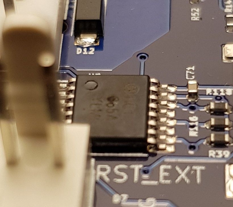
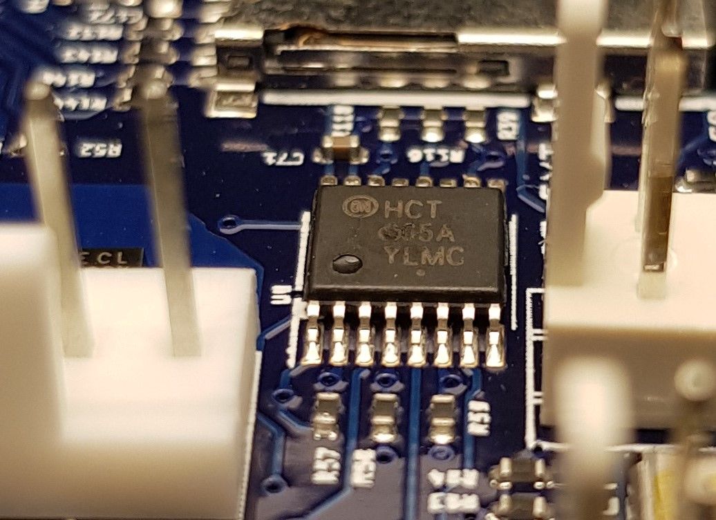
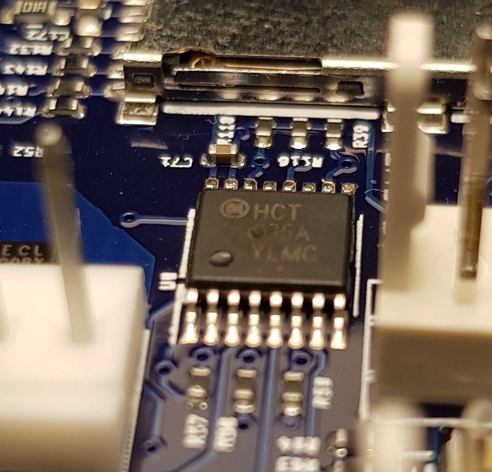
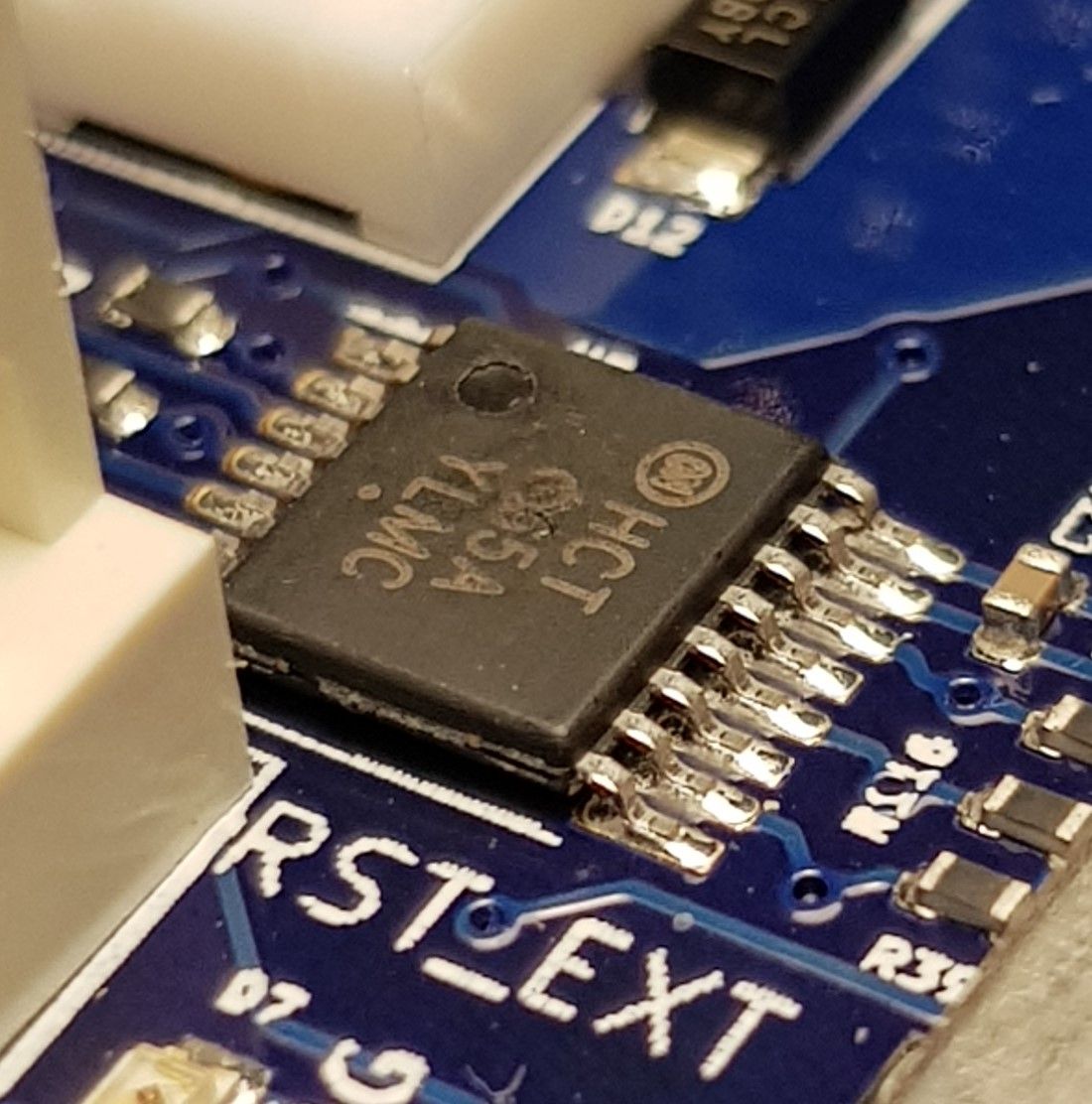
Does that chip next to R57 have a pock mark on it or is that just an artifact of the camera?
-
@phaedrux Thanks for pointing this out, I guess it comes with experience. I just had a look at it, there is something but I cannot say if it is a pock mark or a bulged. I will take a look at it tomorrow under daylight and post pictures.
Thank you.
-
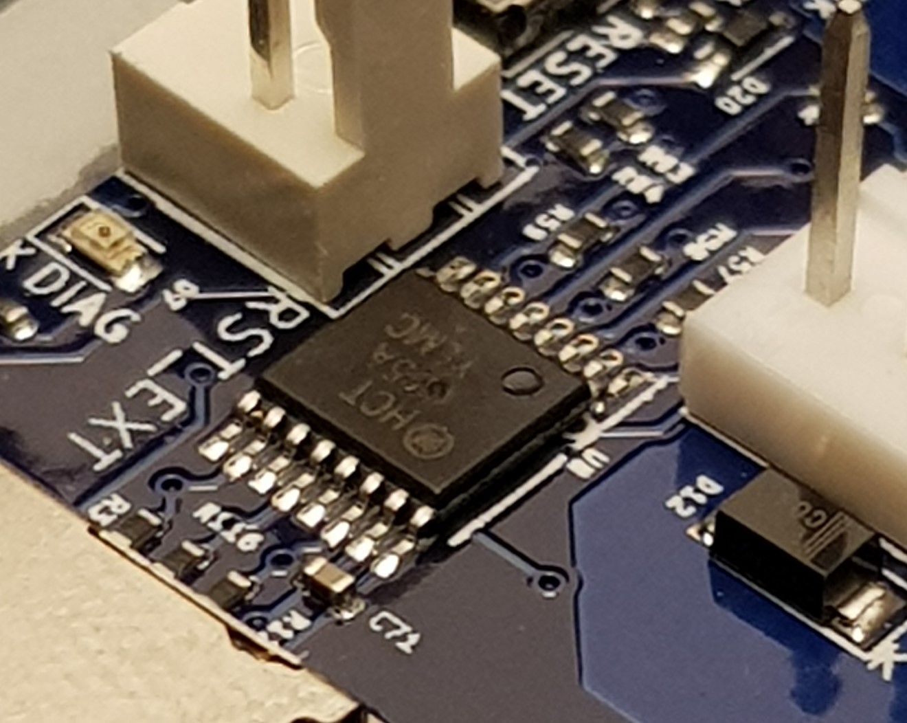
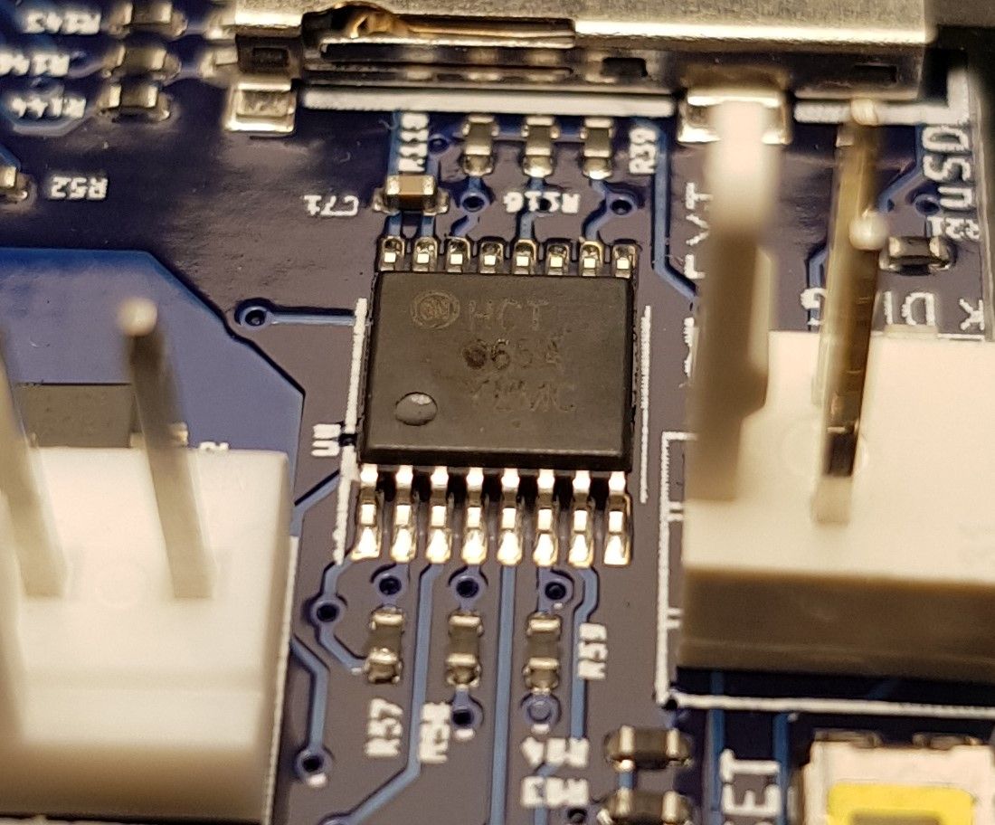
@dc42 please take a look at the close up pictures of the 74HCT365 chip. Can this be the cause for the fault?
Could you please guide me where to place the test leads to measure voltage for R115, R40, R53 and R57. I posted location pictures for the components in my previous post.
Thank you.
-
@kvi94 those pock marks look suspicious to me. I've Just examined three MB6HC boards, and on those boards I can read the figure 3 clearly at that location on the chip.
To measure the voltage that the driver is feeding to the mosfet, measure between one end of the mosfet gate resistor (e.g. R115) and ground.
Duet WiFi hardware designer and firmware engineer
Please do not ask me for Duet support via PM or email, use the forum
http://www.escher3d.com, https://miscsolutions.wordpress.com -
@dc42 said in Heaters will not turn on:
To measure the voltage that the driver is feeding to the mosfet, measure between one end of the mosfet gate resistor (e.g. R115) and ground.
@dc42 As I will be doing this while it is powered via USB, using the input GND terminal is fine? Additionally, should I set the port active with a temperature and measure or measure at idle?
-
@kvi94 yes you can use the VIN ground terminal, or the middle pin of any of the IO connectors.
Duet WiFi hardware designer and firmware engineer
Please do not ask me for Duet support via PM or email, use the forum
http://www.escher3d.com, https://miscsolutions.wordpress.com -
@dc42 Please find below the voltage of the resistors when both output are off.
R40 = 0.001V
R115 = 0.025VR53 = 0.032V
R57 = 0.001V -
@dc42 I managed to measure the voltage when the heaters are in active state by the firmware, the reading are as follows:
R40 = 0.001V
R115 = 0.025VR53 = 0.585V
R57 = 0.004V -
@dc42 did you manage to take a look at the values? What does it suggest?
Thank you.
-
@kvi94 if you are sure that the heaters were on when you took the measurements and had not yet faulted, then it looks like those drivers have failed. Please email warranty@duet3d.com with a link to this thread.
Duet WiFi hardware designer and firmware engineer
Please do not ask me for Duet support via PM or email, use the forum
http://www.escher3d.com, https://miscsolutions.wordpress.com -
@dc42 I had someone to keep an eye on DWC for any fault while I took the measurements, so I am pretty confident they had not faulted.
@dc42 said in Heaters will not turn on:
Please email warranty@duet3d.com with a link to this thread.
Alright, I will get this done.
Thank you.