Heaters will not turn on
-
@deckingman yes I did put back R, C and D parameters. I have measured the voltage, across V_OUT0 and OUT0_NEG I read -0.03V and across V_FUSED and OUT1_NEG I read 0V. Is that what you meant by Vin and gnd?
Is the heaters section in my config.g fine? Am I missing a parameter in M950, for it to not physically activate the out0 and out1?
Additionally, I tried assigning out2 as an IO switch using M950 P2 C"out2" and activate it using M42 P2 S1. That did not work and I am not sure whether this is possible.
I really hope it is not the FET driver that is faulty. Tomorrow I will try and plug my part cooling fan in out4 to test.
-
@kvi94 Sounds like a blown fuse to me....
-
@deckingman you mean the blade fuses? I am reading 0.3 ohm across each. Guess they are fine.
-
I tried my part cooling fan on out4, out5 and out6, it does not work.
Is there a way to perform a built-in self test?
Thank you.
-
@T3P3Tony @dc42 please help me! Is there anything I can do to test whether the mosfet driver is causing this issue?
I have powered this board 4-5 months back, before that it sat in the antistatic bag and box while I was assembling my printer. I was at the calibration stage of my build, so I have not even got the chance to use the board properly to print something.
Thank you.
-
@kvi94 how did you have the buck converter connected? Th 18.8V minimum supply voltage is suspicious.
Your M307 parameters in config.g are different for heaters 0 and 1, yet the expected rate of temperature rise reported in the error messages are the same. That doesn't look right, so I think something is going wrong with the configuration. Here are two things you can do to check:
- Send the following commands and check that the values reported are the same as you set in config.g:
M950 H0
M307 H0
M950 H1
M307 H1- Send this command:
M98 P"config.g"
and see if any error messages result.
The chips that drives the heater 0 and heater 1 mosfet are the 74HCT365 or 74HCT367 chips labelled U8 and U9. I advise against trying to measure voltages on those chips, because if you short pins together then you are likely to feed 5V into the microcontroller. You can measure the gate drive voltage to the mosfets on resistors R115 (for OUT0) and R40 (for OUT1). These resistors are close to the respective mosfets. You can measure the input voltages to the buffer ICs on R53 (for OUT0) and R57 (for OUT1).
Duet WiFi hardware designer and firmware engineer
Please do not ask me for Duet support via PM or email, use the forum
http://www.escher3d.com, https://miscsolutions.wordpress.com -
@dc42 the buck converter was connected on the same line that feeds the duet board. Since I removed it, I now get 23.8V minimum. I will wire it on spare port of my PSU.
@dc42 said in Heaters will not turn on:
Send the following commands and check that the values reported are the same as you set in config.g:
M950 H0
M307 H0
M950 H1
M307 H1Send this command:
M98 P"config.g"
Can I do this while the board is powered via USB? I disconnected the board to inspect for any physical damage, but i see none.
@dc42 said in Heaters will not turn on:
The chips that drives the heater 0 and heater 1 mosfet are the 74HCT365 or 74HCT367 chips labelled U8 and U9. I advise against trying to measure voltages on those chips, because if you short pins together then you are likely to feed 5V into the microcontroller. You can measure the gate drive voltage to the mosfets on resistors R115 (for OUT0) and R40 (for OUT1). These resistors are close to the respective mosfets. You can measure the input voltages to the buffer ICs on R53 (for OUT0) and R57 (for OUT1).
Yes, I went through the schematics and located the 2 74HCT365 drivers on the board. Can I measured the required pins while powered via USB? or should it be powered by 24V?
And regarding the expected temperature rise, it is not constant every time I tried. At times it is 1.7deg, 1.3deg or 0.3deg.
Additionally, I want to confirm when does the LED next to out0-out3 turns on? Because whenever I set the heater active with a temperature the LED are off.
Thank you.
-
@kvi94 as I said before, do not try to measure the voltages on the pins of those chips. Measure them on the resistors instead. You can use USB power, but expect the 5V rail voltage to be a little low, perhaps 4.5V.
Duet WiFi hardware designer and firmware engineer
Please do not ask me for Duet support via PM or email, use the forum
http://www.escher3d.com, https://miscsolutions.wordpress.com -
@dc42 sure, I will locate the resistors and confirm with you in a while.
Thank you.
-
@dc42 please find below the output for M950 and M307 commands
M950 H0
Heater 0 pin out0 frequency 250Hz, sensor 0
M307 H0 Heater 0 model: heating rate 0.593, cooling time constant 389.7, dead time 3.93, max PWM 1.00, calibration voltage 0.0, mode PID Computed PID parameters: setpoint change: P76.6, I1.957, D210.7, load change: P76.6, I5.418, D210.7M950 H1 Heater 1 pin out1 frequency 250Hz, sensor 1M307 H1 Heater 1 model: heating rate 1.680, cooling time constant 233.0/193.0, dead time 6.75, max PWM 1.00, calibration voltage 23.7, mode PID Computed PID parameters: setpoint change: P15.7, I0.397, D74.4, load change: P15.7, I0.865, D74.4The PID parameters are the same as in my config.g for H0 and H1.
Below is output for M98
M98 P"config.g" HTTP is enabled on port 80 FTP is disabled TELNET is disabled -
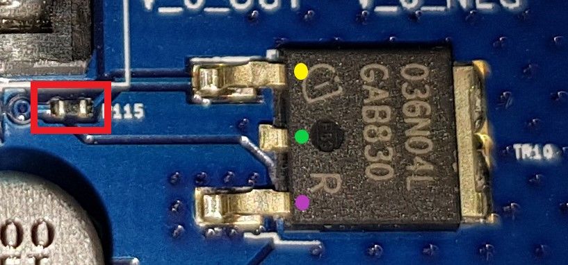
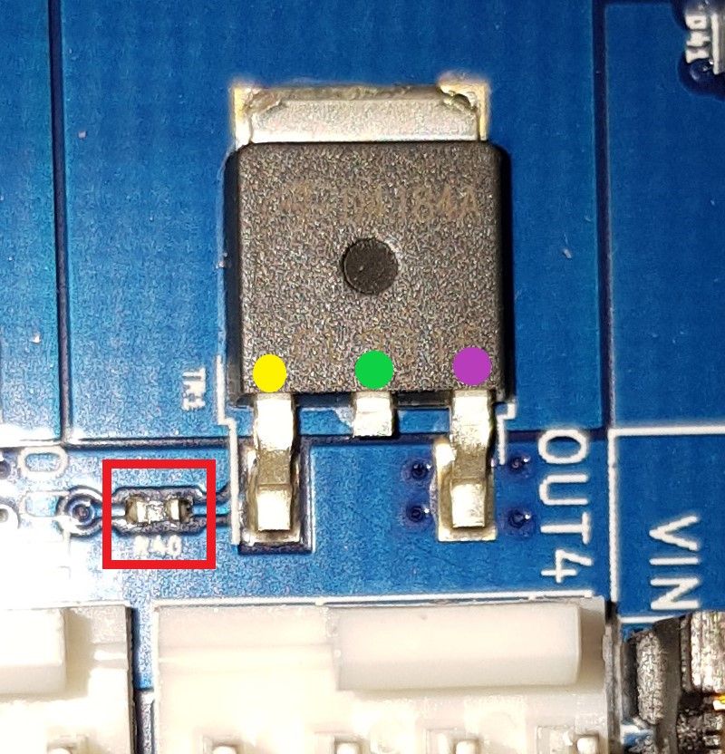
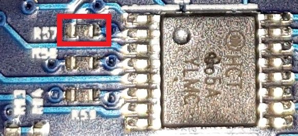
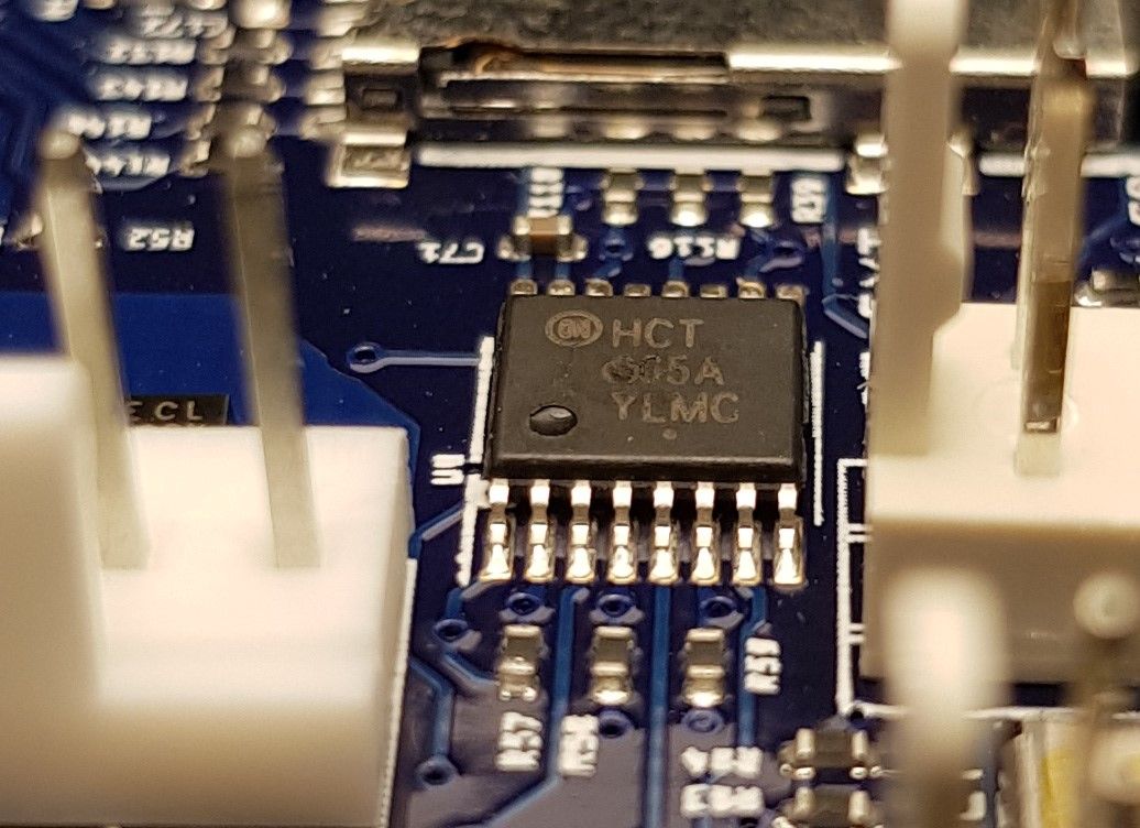
@dc42 please find below pictures for R115, R40 and R57. Is R53 located next to temp3 pin by chance?
I have put 3 coloured dots on the mosfet pins for R115 and R40, if you do not mind could you please tell me explicitly where to measure the required voltage. It is my first time doing this at this scale, I really do not want to mess up things since this situation is already stressing me out.
Regarding R57, should I measure across the 2 terminals of the resistor itself?
Thank you.
R115
R40
R57
-
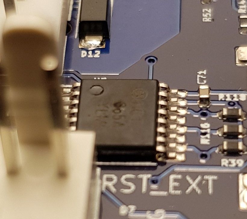
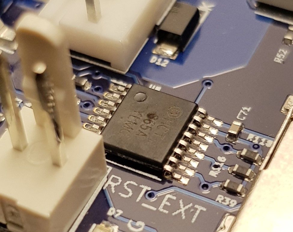
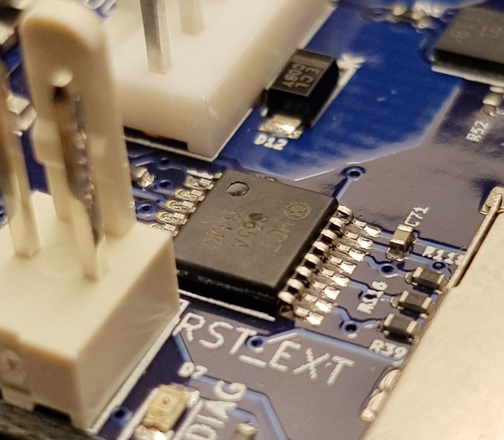
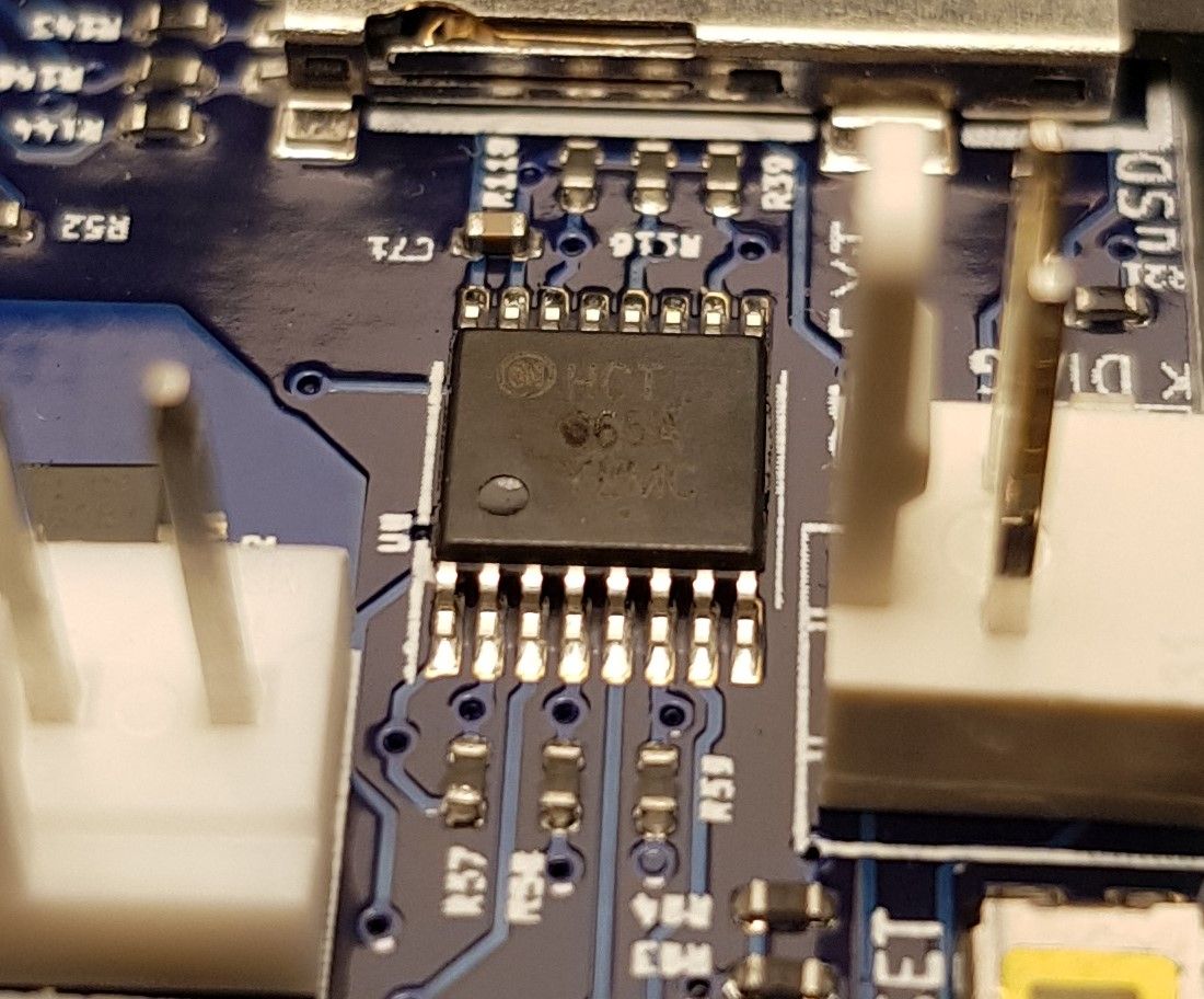
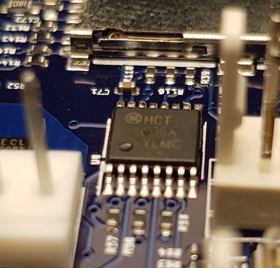
Does that chip next to R57 have a pock mark on it or is that just an artifact of the camera?
-
@phaedrux Thanks for pointing this out, I guess it comes with experience. I just had a look at it, there is something but I cannot say if it is a pock mark or a bulged. I will take a look at it tomorrow under daylight and post pictures.
Thank you.
-
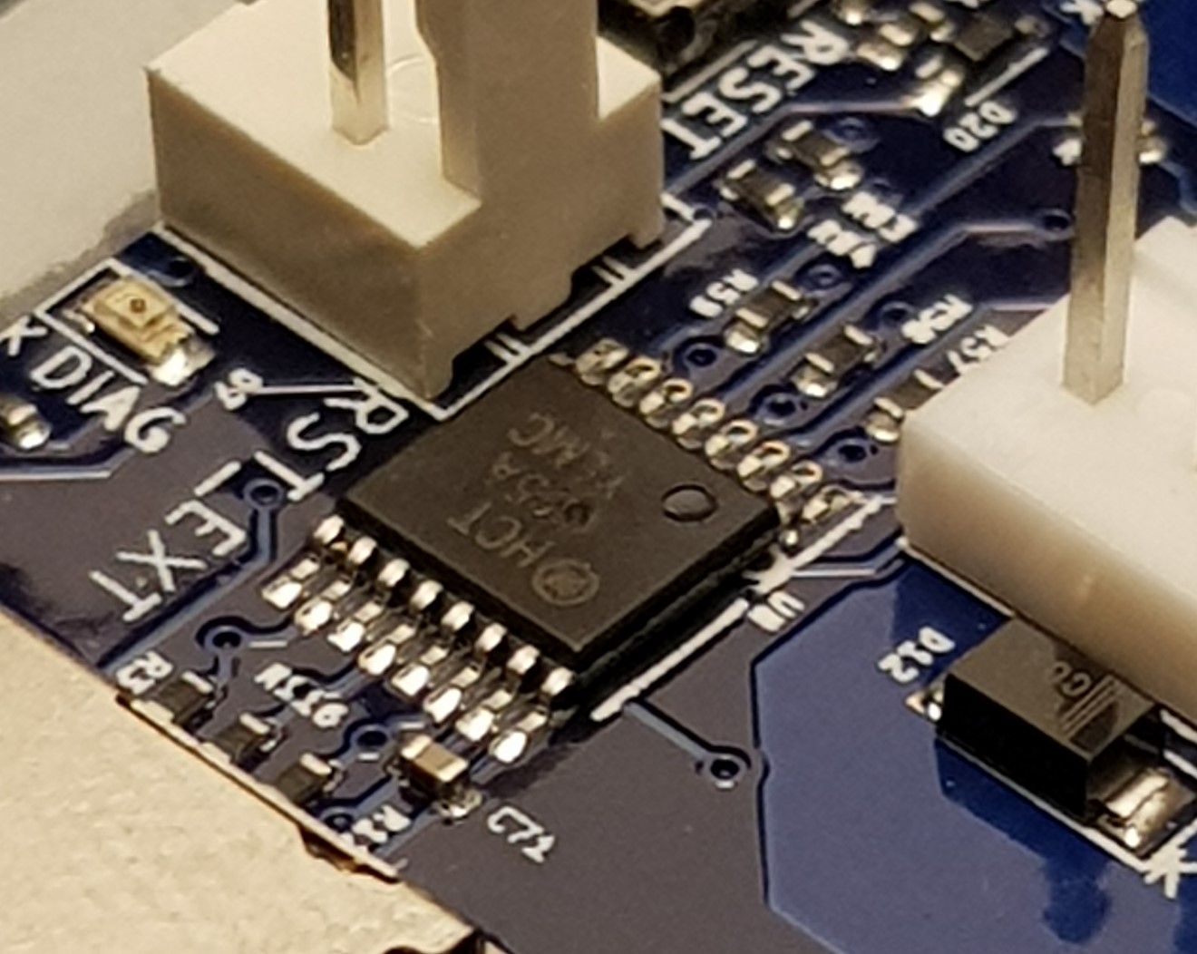
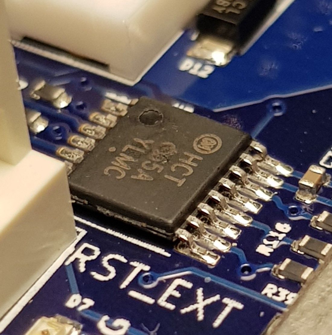
@dc42 please take a look at the close up pictures of the 74HCT365 chip. Can this be the cause for the fault?
Could you please guide me where to place the test leads to measure voltage for R115, R40, R53 and R57. I posted location pictures for the components in my previous post.
Thank you.
-
@kvi94 those pock marks look suspicious to me. I've Just examined three MB6HC boards, and on those boards I can read the figure 3 clearly at that location on the chip.
To measure the voltage that the driver is feeding to the mosfet, measure between one end of the mosfet gate resistor (e.g. R115) and ground.
Duet WiFi hardware designer and firmware engineer
Please do not ask me for Duet support via PM or email, use the forum
http://www.escher3d.com, https://miscsolutions.wordpress.com -
@dc42 said in Heaters will not turn on:
To measure the voltage that the driver is feeding to the mosfet, measure between one end of the mosfet gate resistor (e.g. R115) and ground.
@dc42 As I will be doing this while it is powered via USB, using the input GND terminal is fine? Additionally, should I set the port active with a temperature and measure or measure at idle?
-
@kvi94 yes you can use the VIN ground terminal, or the middle pin of any of the IO connectors.
Duet WiFi hardware designer and firmware engineer
Please do not ask me for Duet support via PM or email, use the forum
http://www.escher3d.com, https://miscsolutions.wordpress.com -
@dc42 Please find below the voltage of the resistors when both output are off.
R40 = 0.001V
R115 = 0.025VR53 = 0.032V
R57 = 0.001V -
@dc42 I managed to measure the voltage when the heaters are in active state by the firmware, the reading are as follows:
R40 = 0.001V
R115 = 0.025VR53 = 0.585V
R57 = 0.004V -
@dc42 did you manage to take a look at the values? What does it suggest?
Thank you.