setting the offsets - table and probe
-
So while reviving the printer with Duet 0.8.5 board I've added the probe and now I'm trying to set up the offsets. Can someone help me out with it? I'm a bit baffled whether machine or wcs is being used, whether the nozzle is offset to probe or the other way, etc.
I can set those up separately, but in conjunction I'm a bit lost - which is a bummer as I think I could get most of the problems with this machine solved if I can get automatic mesh bed leveling to work.
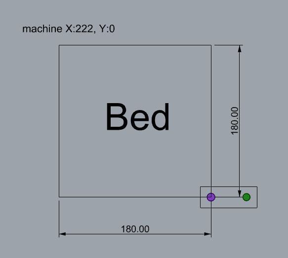
So just to explain a bit better what I'm working on here's a simple sketch that hopefully illustrates the setup:
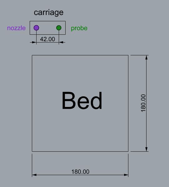
So I have a 180 x 180 table and a rather chunky carriage that has the whole "extruding" part with nozzle on the end, and 42mm to the right Bltouch probe. The carriage can move to the right and to the left of the table - it's a gate style of machine so there's a bit of room on the sides.
So here's the position after homing (machine coordinates 0,0 -I'll skip Z):
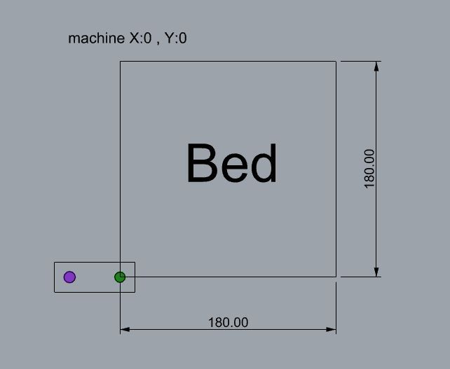
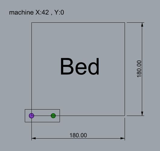
The nozzle is hanging outside the table, to the left, while probe is barely hanging above the corner (which allows it to measure this point).So to get the nozzle on the table I need to move it 42mm in the X (machine coordinates 42,0):
To get the measurement of the height on the right side of the table I need to move carriage to machine coordinates 180,0.
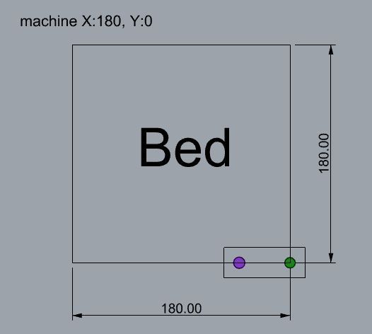
But to actually print there I need to move the carriage to machine coordinates 222,0 :
So how do I actually set axis limits (M208), probe offset and mesh grid (M557)to get let's say 4x4 grid of points and that would translate position of the probe into position of the nozzle .... and that would allow me to use the whole table.
I assume that once you do it one time this becomes easy but for now I'm confused. -
https://docs.duet3d.com/en/User_manual/Tuning/Bed_origin
There are a few ways to setup the bed origin. Is your nozzle off the bed when the endstops are triggered? 0,0 should either be the bottom left corner of your bed, or the center of the bed. Up to you. M208 minimum can be negative in case the low end endstop is off the edge of the bed.
The probe offset from the nozzle should be measured and entered into G31.
To set a M557 grid, the easiest way is to just match the M208 bed size and let it figure out what it can reach and skip the points it can't. If you don't want the warnings about skipping points you can adjust the M557 grid size to take the G31 XY offset into account.
-
@phaedrux
thank you for the reply Phaedrux.@phaedrux said in setting the offsets - table and probe:
you can adjust the M557 grid size to take the G31 XY offset into account
-- that's basically what I can't figure out.
Currently when I have maximum / minimum travels set up so the nozzle reaches every point on the build plate , the probe can't - and thus it is skipping points.
How do you fix that?Of course, I can set it up in a way that there will be no probing on the left edge of the table , but that limits the purpose of the whole setup - especially considering how far the probe is in relation to the nozzle (I'd shave 42 mm on the left side).
As the carriage has enough travel to reach those areas with both probe and nozzle I wonder whether there's a way to set it up. -
@przemas said in setting the offsets - table and probe:
Currently when I have maximum / minimum travels set up so the nozzle reaches every point on the build plate , the probe can't - and thus it is skipping points.
How do you fix that?Do you have the physical room for the nozzle to move outside the bed area to allow the probe to reach the entire bed? If so, you can alter the M208 to allow that for probing. The M557 would still be the extents of the bed area only.