Minimizing the effect of Smart Effector flex/bending?
-
Okay, so I've been through various designs of my Orbiter v2 adapter:
- Mounted the Orbiter on a tilted platform (~7cm) on top of the PCB and the 55mm spacing.
<-- the big lever leads to the nozzle tilting when you even so ever slightly tap the Orbiter with your little finger.
- Printed a 2 piece adapter (PLA-CF, noticably stiffer than normal PLA) and 80mm width, mounting the SE on the 80mm adapter piece. Mounted the Orbiter on another rigid top-piece without any connection to the SE.
<----- resulted in the distance of the Orbiter and thee Smart Effector to vary. When extruding you could see the PCB bend away under the pressure. Lead to massive extrusion problems, but ringing was just a little bit worse than bowden. But due to the extrusion problems unusable.
- mounting the SE and the Orbiter on different platforms. SE only to the 80mm adapter, Orbiter with 0 offset fixed by 3 screws directly to the 3 mounting holes. Same problem as #1, even the faintest tap to the nozzle or Orbiter led to the whole PCB flexing. But even worse than #1. I suspect that #1 also led to the rods (Haydn 440mm) flexing which damped out the whole thing?
Last thing to try: one solid oiece, fixing both the outer and inner holes on the SE as well as the Orbiter. As I didn't experience ANY problems at all eith sensitivity on 1-3 thos might actually still work..
Any other ideas?
-
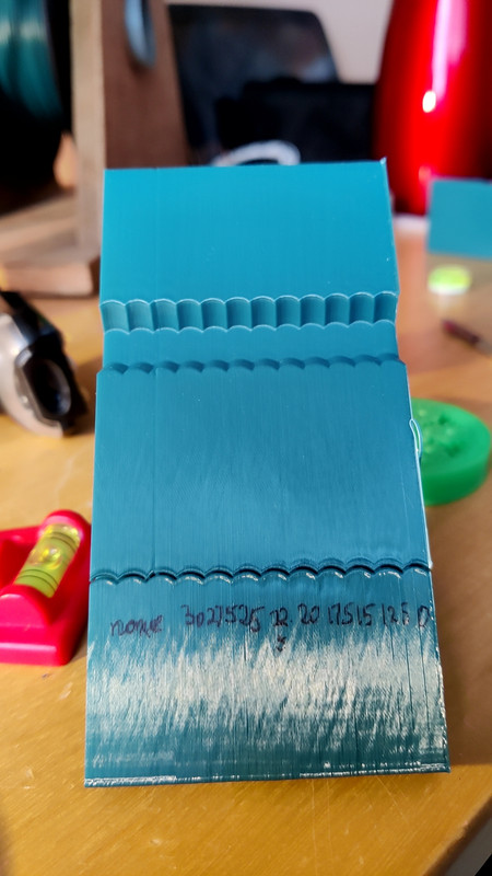
@bberger for me, 55mm arm spacing with 12mm extension (https://www.thingiverse.com/thing:5239585) gives enough room for the orbiter 2 to be horizontal and close to the hotend, and to cover a 250mm diameter bed. I see much less ringing than the bowden setup - this is a frequency scan on the ringing tower single wall at 80mm/sec:
 ,
,
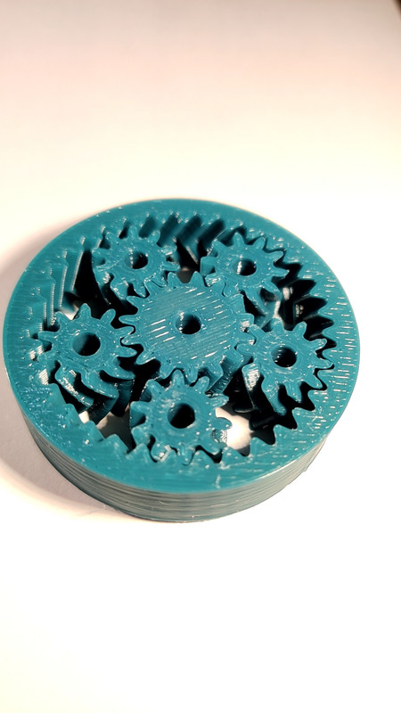
I used a cf/petg filament (Colorfabb XT-CF20) for the extension, and I think clamping the pcb between extension pieces above and below stiffens the assembly. My most recent 19 point G32 gave deviation of 0.015. The sensitivity of the SE did not change - I have two SE with different optimal Z offsets, but those respective offsets remained exactly the same with the extension. I should add that I previously had an orbiter 1.5 on a 800mm bowden, which I have left in place, feeding the bowden tube into the orbiter 2 on the SE, and driving them off E0 and E1 - I haven't yet tried with the orbiter 2 alone. With the dual extruder setup, I am seeing much cleaner prints - this is a planetary gear that previously required quite push to get it moving, but moves freely straight off the printer now.

-
@adrian52 I know your design from another thread which inspired me to test #3.
Ultimately I want my adapter to be milled out of a CF sheet but I need to solve the "wobbling" hotend first and see how far I can go with clamping the SE inner holes down without affecting sensitivity. So far I have zero issues with the Z-Probe and 3 screws + a nut clamping down my Rapido AND my Orbiter.
I'll go probably try to go full cage next try to restrict the pushing force while leaving 0.1mm for the SE to bend "up" while touching down.
Don't get me wrong, you can use the Orbiter (or Sherpa or LGX Lite) no problem of you turn down accelerations to 1.5k and print slow (<= 100mms). Using CF filament for some reason also helps.
I am trying to push the limit here. I want printability at 5k+ acceleration as I do lots of prototyping projects for my other hobby (simracing) with bigger parts..
But I also love to get mesmerized by watching Delta kinematics. It's as exciting as watching a TV show for me. Even after years. I'm on a mission to max out my Delta

-
For anyone wondering, this is what I'm concerned about:
https://youtu.be/504USJkVbjc