DIY Fan Smoother
-
@o_lampe, increasing the current 'rating' is a good idea. The small order of 5 units already went out but I will look into it. May need to increase the 1uf capacitor and understand the max peak current drawn from the controller. I have a MicroCAP simulation of it. My look also if EasyEDA simulation can handle it so everything is in one package.
@o_lampe, this board was not designed to be duet specific but doughtier board is an interesting idea. Need to find proper connectors and make sure the inductors are not too heavy.
@JoergS5, my goal with this order is to test dc42's idea and have a basic design that people can use. Adapting it to other form factors, number of channels, and so on should be easy. I did the entire design online using EasyEDA and the design can be copied and modified, no software required.
-
@zapta said in DIY Fan Smoother:
did the entire design online using EasyEDA
I thought so after our discussion in the other thread. You asked for feedback, this were my ideas. As always it depends on the 3D printer construction which is the best solution. Did you use simulations and which to verify the circuit? The circuit is not too complicated - how did you come to the motor analyzer solution e. g.? Trial and error, an existing template, experience?
-
@joergs5, originally I simulated using MicroCap (discussed in another recent thread here) for simulation and today also simulated it in EasyCad. EasyCad simulation is not as capable as MicroCap (e.g. limited number of simulation steps or I couldn't figure out how to find a Schottky diode model, or viewing result graph is limited with an 'osciloscope' widget) but it gave reasonable results.
As for the motor analyzer, the challenge was not the electric circuit (simple analog current sensors that are connected to ADC inputs of a microcontroller) but the user interface. The last one was my fourth iteration with different microcontroller, TFT and user interface library combinations, and I like to to a point that I don't plan to change. I learned a lot along the way
")
For me, the best way of learning is setting a goal of something I want to build and solving the problems on the way.
-
@zapta thank you for your description of your development process, it's valuable information!
-
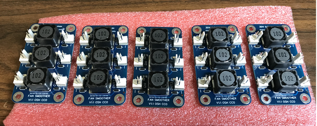
The five board arrived from JLCPCB, assembled, including the hand soldered connectors, and looks good. I tested them with 50Khz PWM from the duet and they seem to work well, providing to the fan DC voltage. The voltage is perfectly clean when I hold that fan by hand and had some motor injected ripple when the motor turns but it seems to be OK.
One of my fan responses well to PWM so the board didn't make a significant change. Another one doesn't respond well to low % PWM and the board fixes that with much better control at low %.
If you have fans that don't respond well and you like to try this board, I can send you for no charge, but please report your finding here. The behavior of fan motors to PWM varies a lot by vendor and model so the more reports we get the better.
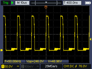
50Khz PWM from the duet
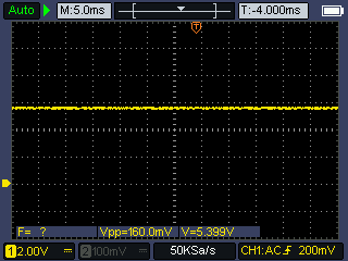
Output voltage if I stop the fan by hand
Output voltage if the fan turns. The 300Hz frequency depends on the fan speed.
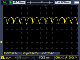
BTW, the last screenshot with the fan speed related signal suggests that's it's possible to extract a tachometer signal from a 2 wires brushless fan. This could be interesting project, e.g. to detect fan failures.
-
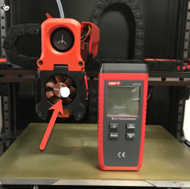
BTW, this is how I measure the fan's speed, with a white dot sticker. Works well.
-
@zapta I'm interested to buy a board!
-
@zapta
I'm interested to buy one too.I've got a 24v pump that don't like pwm...
-
@tech-raton , @cosmowave , please send me a direct message with your name and address and I will mail you one board each.
-
@zapta I received the board.
The pump starts smoothly at 20% and is at full speed at 92%. Far better!Thank you very much...
-
Thanks for the update @tech-raton, I am glad that it works for you.
It's a simple circuit (proposed by @dc42) and fully assembled boards can be ordered from directly JLCPCB.