(Solved) Probe reach area
-
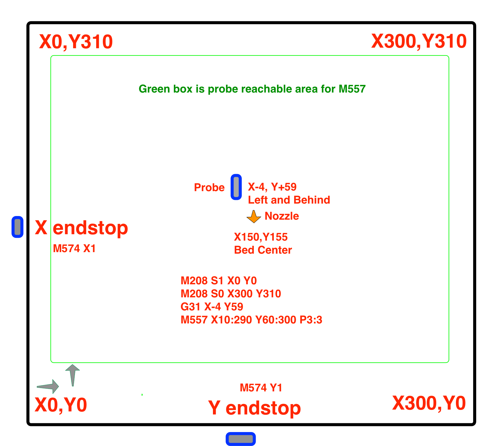
@fcwilt The picture I attached shows the movements of my printer. I don't really understand the point of right and left. The firmware should determine the directions based on X min and Y min. The probe is towards X max and Y max. It shouldn't matter right or left as long as the offset is in correct value ( + or -).
In my case X max is on the left in the picture.
Y max is on the front in the picture. -
@rajaakahel said in Probe reach area:
@fcwilt The picture I attached shows the movements of my printer. I don't really understand the point of right and left. The firmware should determine the directions based on X min and Y min. The probe is towards X max and Y max. It shouldn't matter right or left as long as the offset is in correct value ( + or -).
In my case X max is on the left in the picture.
Y max is on the front in the picture.Regards the probe:
If the probe is towards X max and Y max then the offsets are positive which is what you have.
And the reason it cannot probe at X = 0 or Y = 12 is as I stated.
Regards X and Y movement:
The standard for movement is as I stated. You are free to ignore the standard as you have. But when conversing with others it may lead to confusion.
Frederick
-
@fcwilt Thanks for the input, but again my problem is why it's not reaching the end towards Y max.
-
@rajaakahel said in Probe reach area:
@fcwilt Thanks for the input, but again my problem is why it's not reaching the end towards Y max.
Why do you think that is the case?
Every error I see listed is at X=0 or Y=12?
Where is the error you are speaking of?
Frederick
-
@rajaakahel said in Probe reach area:
I don't really understand the point of right and left. The firmware should determine the directions based on X min and Y min. The probe is towards X max and Y max. It shouldn't matter right or left as long as the offset is in correct value ( + or -).
No, this is not correct and is the source of your problem.
@phaedrux said in Probe reach area:
Remember, -X should move left, +X should move right
-Y should move to the nozzle to the front of the bed, +Y to the back.This is a fact of the cartesian coordinate system used by the printer, and the CAD and slicer software we use with it. This is important in order to have printed parts that match the source model and not be reversed.
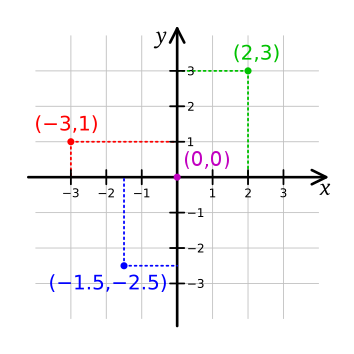
See these image examples of a right hand coordinate system.
@rajaakahel said in Probe reach area:
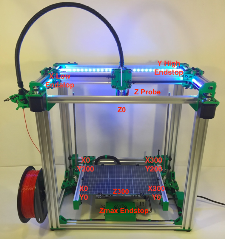
In my case, when I'm in front of the printer, X mini endstop is on my right, and the probe is on the other side of the nozzle (my left).
And Y mini endstop is in the back right corner, +Y moves forward towards me.If the X endstop is on the right side, the printer must move to the right in the positive direction in the homing files. The endstop must be configured as M574 X2 to be on the high end of travel. If the probe is on the left of the nozzle it's offset is negative.
If the Y endstop is at the back, it is on the high end and must be M574 Y2. Y+ moves should move to the back. Homing moves must be in the positive direction.
Before you can determine the probe offset you need to get your coordinate system in order.
For me to provide further guidance please post your config.g and homing files.
-
@phaedrux
Thanks for the input, I'll modify the firmware so that it uses my endstops as max instead of min. And will change the X&Y offsets to negative. Then I'll test the probing reach.
However I never got a reversed printed part with my current setup (I printed my owen designs and STLs from the internet).
All texts and images are printed correctly.
I'll get back with my configurations and homing files. -
@rajaakahel said in Probe reach area:
However I never got a reversed printed part with my current setup (I printed my owen designs and STLs from the internet).
This is likely because both axis are flipped, which has the effect of rotating the coordinate system 180 degrees.
-
@phaedrux
Thank you again! now it's doing better after changing the direction of the coordinate to as you mentioned.
Strange that I have never seen a topic explaining the importance of this issue. -
Well it is mentioned in various places
https://docs.duet3d.com/en/User_manual/Tuning/Bed_origin
https://docs.duet3d.com/en/User_manual/Machine_configuration/Configuration_coreXY -
@phaedrux Thanks for the link. Never seen this documentation website before.