Number of teeth engaged
-
@fma All good then!
-
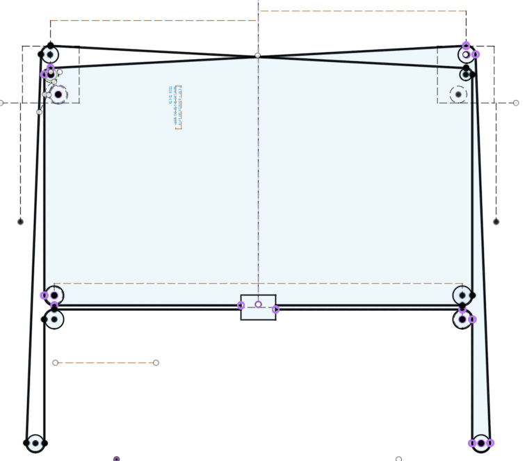
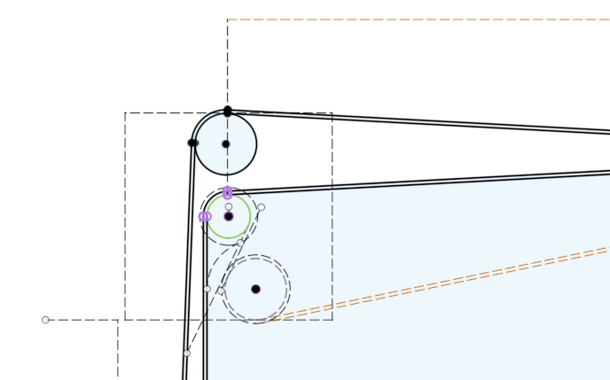
On the CoreXY I recently designed, I started with 90 degrees of engagement on the motor gear and had some issues with jumping teeth, so I added another idler to get more wrap. Ultimately I found my gantry was jamming on certain moves and causing my problem, but I left the extra idler in and have not had any issues.
Here's my original layout and extra idler I added (dashed lines)
Since you are designing, some other things I decided to do that you might consider. My motors are also at the rear corners.
- Make your idler pulleys from two flanged bearings (I used F606ZZ pulleys with a 10mm belt, which allow a 6mm screw through the hub).
- 10mm belt - the costs are not much more and you get much less stretch.
- Twisted belt configuration. At the back of the machine, where the upper and lower belts cross, if each belt is given a 180 degree twist in that segment, the upper and lower belts can be moved closer together vertically. The center of my upper belt pulley is only 3mm higher than the center of my lower belt pulley. My tallest standoff for any pulley is 3mm. I don't worry about the hubs bending. People will say bad things about twisted belts. I've been running this printer for several months without any issues.
- The only two places that the belts need to be parallel are the segments that connect to moving pulleys - those that move the gantry, and the segments that move the printhead on the gantry.
- If you have access to a laser cutter, I recommend prototyping the corner plates in mdf. I did this and it helped me see several issues that I solved before paying for aluminum. And if you are in the US, check out SendCutSend.com (no affiliation, just a satisfied customer) for inexpensive laser cut aluminum.
Picture of the finished printer without the enclosure:

-
@mikeabuilder said in Number of teeth engaged:
Since you are designing, some other things I decided to do that you might consider. My motors are also at the rear corners.
- Make your idler pulleys from two flanged bearings (I used F606ZZ pulleys with a 10mm belt, which allow a 6mm screw through the hub).
Is it better than Gates idlers?
- 10mm belt - the costs are not much more and you get much less stretch.
This is something I have in mind for a while. My current printer uses 3GT 9mm Gates belts, as I used gears and linear rods/bushing (16mm!!!) from an old Stratasys printer.
So, when I now see 2GT 6mm belts, they look like toys...
- Twisted belt configuration. At the back of the machine, where the upper and lower belts cross, if each belt is given a 180 degree twist in that segment, the upper and lower belts can be moved closer together vertically. The center of my upper belt pulley is only 3mm higher than the center of my lower belt pulley. My tallest standoff for any pulley is 3mm. I don't worry about the hubs bending. People will say bad things about twisted belts. I've been running this printer for several months without any issues.
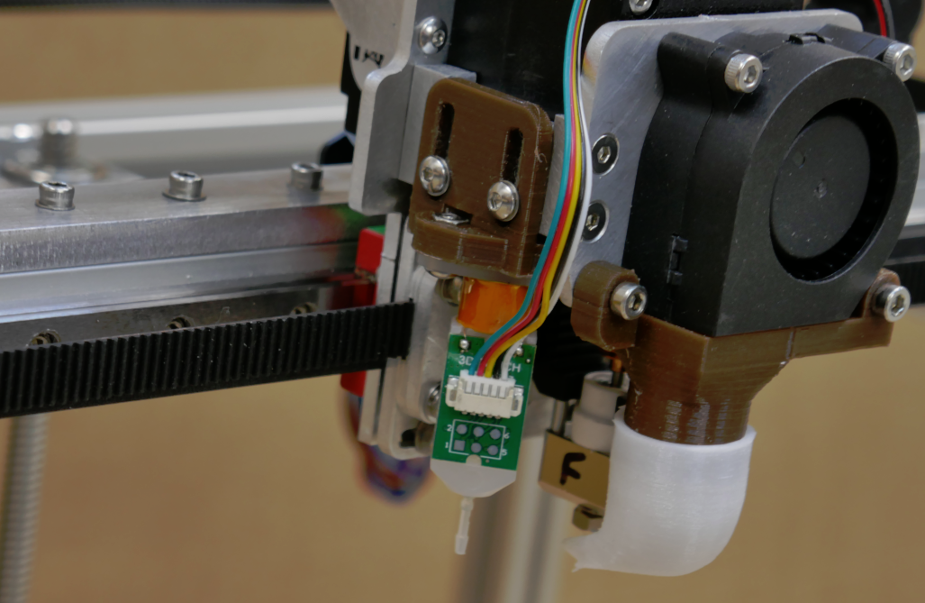
Funny, because my current printer uses the same twisted belts config as yours, with the 180° rotation! I designed a special part, holding a piece of PTFE between the belts, to reduce friction... It works very well for more than 3 years.
- The only two places that the belts need to be parallel are the segments that connect to moving pulleys - those that move the gantry, and the segments that move the printhead on the gantry.
Yep.
- If you have access to a laser cutter, I recommend prototyping the corner plates in mdf. I did this and it helped me see several issues that I solved before paying for aluminum. And if you are in the US, check out SendCutSend.com (no affiliation, just a satisfied customer) for inexpensive laser cut aluminum.
I do have access to a laser cutter, and I plan to prototype the entire machine in wood, and also in PMMA as some parts need to be bent. And I will have access to a waterjet cutter for the final parts
")
Picture of the finished printer without the enclosure:
Nice! Feels solid as a rock! I understand you're not concerned by bending issues!
Thanks for your advices.
-
@fma said in Number of teeth engaged:
Is it better than Gates idlers?
I'm not sure if it's better than gates, but using flanged bearings does allow for more choices of hub and outer pulley diameter.
-
@mikeabuilder Good point!
-
This post is deleted! -
@arnold_r_clark I use stacked belts, too, and avoid adding additional pulleys to adjust belt tension by mounting the motor mounts on slots that allow them to slide.
You could also adjust belt tension at the extruder carriage without adding any extra pulleys.
-
This post is deleted! -
I designed a mechanism that connects my top and bottom belts together into a continuous belt so that the tension in both belts is equalized. And then I use the "sounds and feels" good enough method to set the tension.
-
@mikeabuilder Amazing, I also have a continuous belt, which turns around a free pulley on the carriage, which I then secure with a screw, to get 2 independant belts!
-
@fma - I like the pulley concept but it does require the belts to have zero z-offset, which explains your use of the PTFE belt separator at the crossover point. I separated my belts by 3mm in Z and that leaves me a 1MM gap between the belts at the crossover. Knowing that your PTFE solution works may bring me to a zero Z offset on a future iteration of my design.
-
@mikeabuilder If you stack the belts (12mm vertical) you don't need for them to be in contact at all, and they can share axles...

-
@mrehorstdmd - You're correct. It's all a question of design tradeoffs. For my design, I worried about the way both Z and X offsets in the belts "might" cause unacceptable torques on the print carriage, so I opted for a design that kept the offsets really small at the carriage.
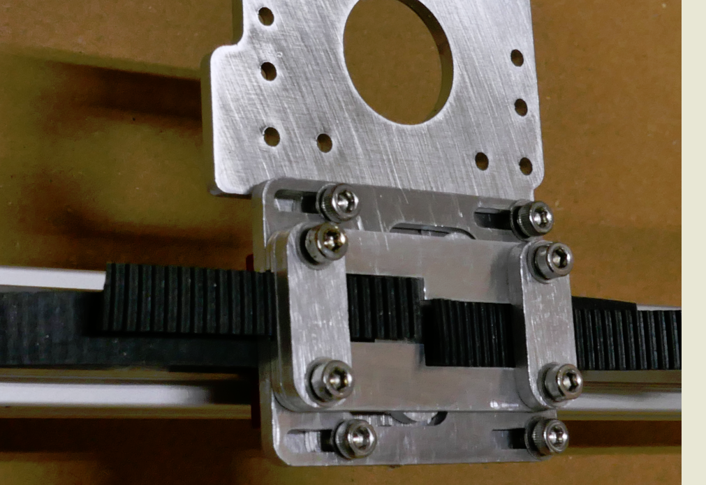
Here's the completed assembly
And here the clamping mechanism behind it where you can see both belts better. The belt centers are offset 3mm in Z and 4mm in Y.
It's great that there are so many variables to play with. Makes lots of opportunities to engineer for fun.
-
A word about idlers (I didn’t quite see if the designs have this): Smooth idler on the tooth side of the belt will cause small but noticeable irregularities on the movement (on one of my prototypes, about 0.02mm).
-
@juku That depends on the diameter of the pulley. I specifically chose F608 bearings for pulleys in my printer because they meet the Gates recommended minimum of 9 teeth in contact with a smooth pulley surface. I get no print artifacts from the smooth pulleys.