What goes to GND (-), V- or ground?
-
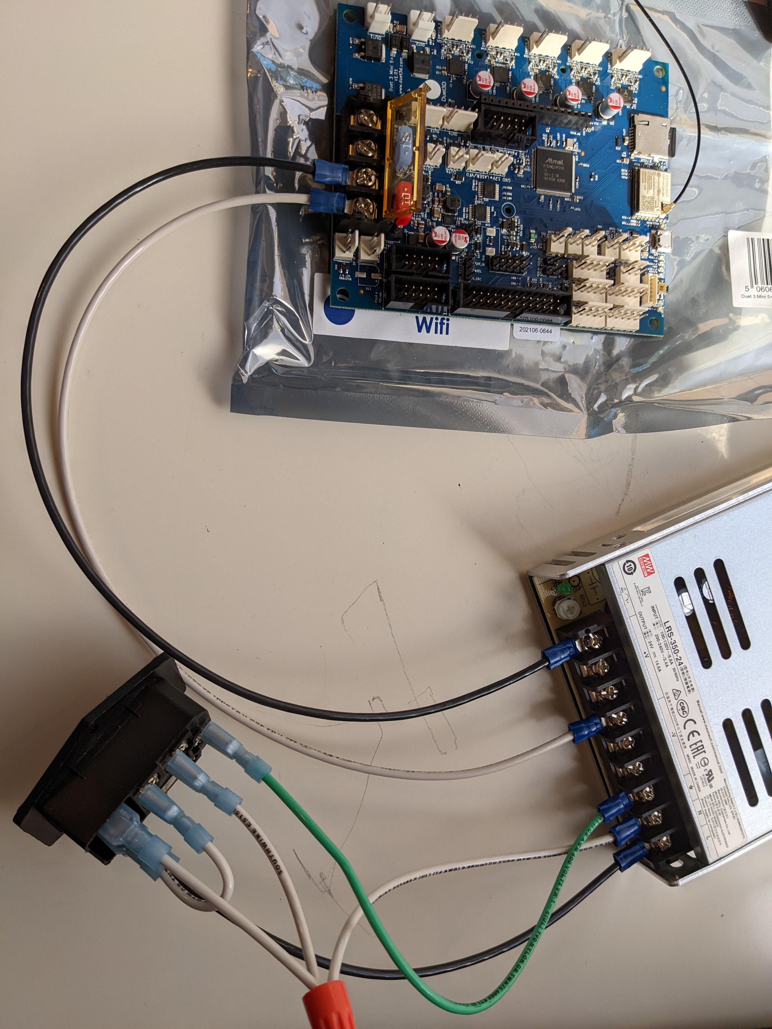
I just hit the electronics portion of my first 3D printer build with a Duet 3 Mini 5+. I think I've wired my switch correctly in front of my PSU. Then I think my PSU V+ goes to the Duet VIN screw.
My confusion is around the GND (-) screw next to it. I assumed my PSU V- would be wired to that, but I'm staring at "GND". I have AC ground going from the wall to the switch to the PSU. I don't see another ground on the Duet. So what goes to GND (-), V- or ground? If it's not ground, how does the Duet get grounded?
I know this must be extremely basic. Thanks in advance for any advice.
-
@elon Hi, so firstly don't worry about asking what might be a simple question better to ask before something goes wrong.
Maybe also post a picture of your wiring to confirm what you've done but, the AC side of the PSU is Earth, Neutral and Live, this should be wired to a fused socket switch.
From the PSU you want a V+ and V- going to the GND and VIN connections on the Duet board.
Now depending on the rest of the hardware in your printer that's all you need with regards to the PSU for now.
Hope that's ok, post a picture to confirm connections.
-
@rushmere3d Thank you! I've connected PSU V- to Duet GND (-). Image attached.
So how does ground work in this situation since it's not directly connected to the Duet and everything else connects to the Duet? It would seem like everything is ungrounded except for the switch and the PSU.
I used 14awg wire but then realized the switch was set up for plugs that typically contain 18awg wire. Does the step up in size after the switch matter?

Thanks again!
-
@elon GND and Earth on the PSU will be connected internally I believe, it's not something I've ever had concerns over.
Of course depending on the printer, you might need to GND the frame or heatbed.
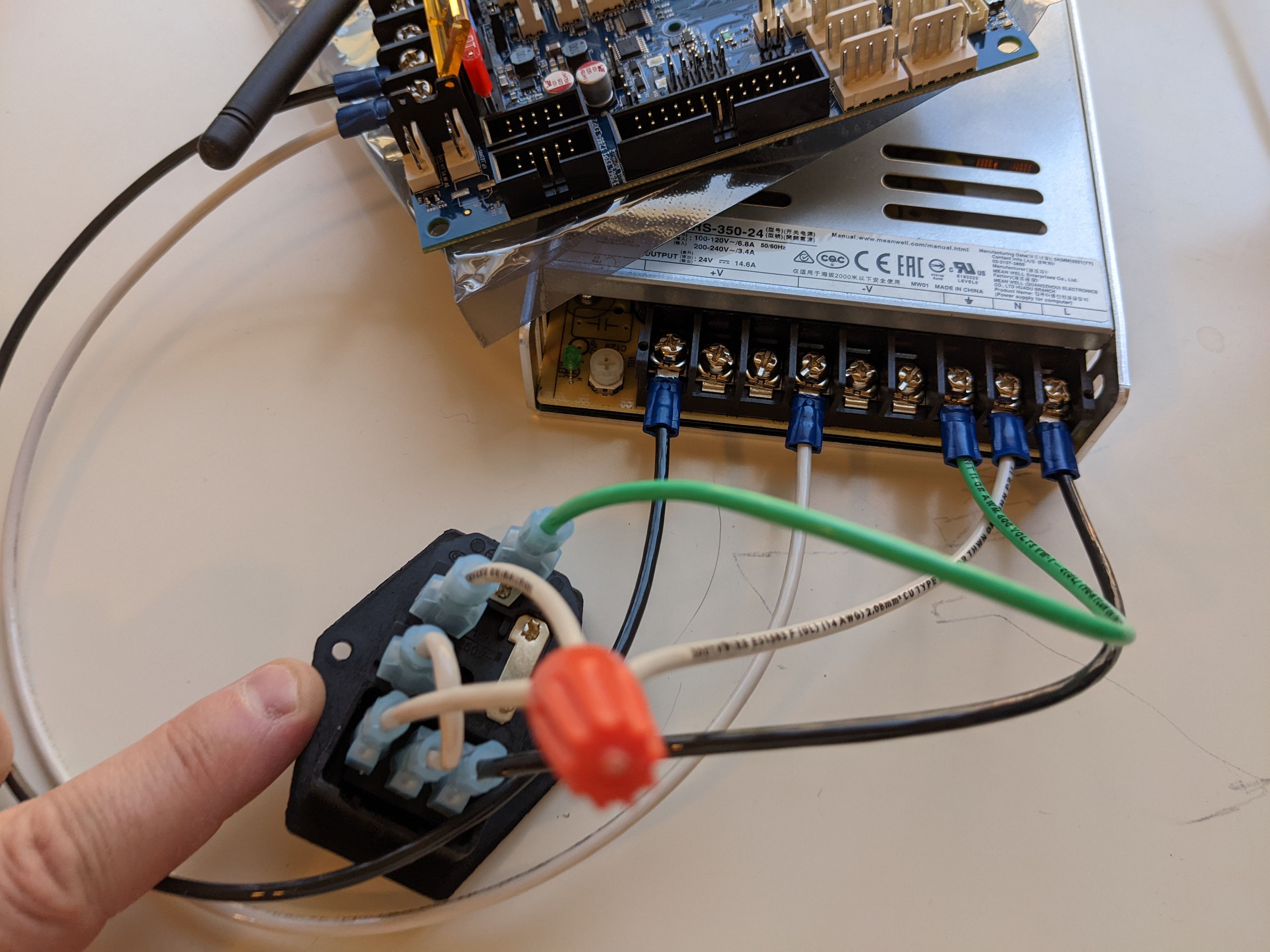
Can you post a better picture of the mains socket/switch wiring? Just want to make sure it's correct.
-
@rushmere3d I've uploaded another picture of the switch. All good?

-
-
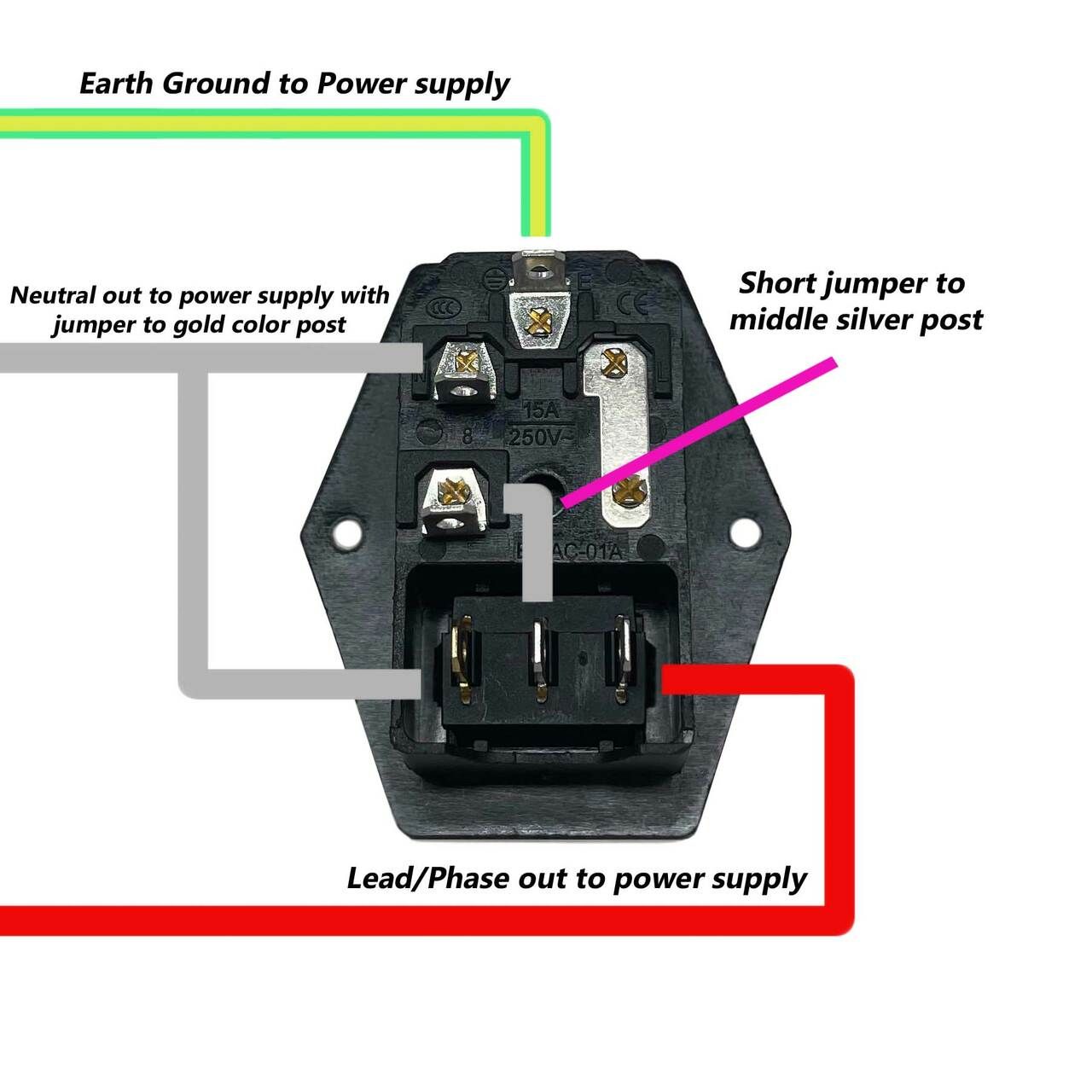
@fcwilt This is the image I followed to wire it, and I think I got it correct, but to be honest it doesn't really make sense to me.
-
@elon said in What goes to GND (-), V- or ground?:
@fcwilt This is the image I followed to wire it, and I think I got it correct, but to be honest it doesn't really make sense to me.
I don't have the kind of switch you have, mine only has two terminals.
Aside from the switch your unit looks like mine and the statements below are based on that.
The green (ground) wire is correct.
The white (neutral) wire to the terminal next to the ground terminal is correct and as noted should connect to the neutral connection on the power supply.
Strictly speaking the short jumper should be a black wire as it is carrying AC hot.
That metal strap is carrying AC hot from the plug to one end of the fuse. The other end of the fuse is that terminal which you have the short jumper connected to.
Do you have any sort of continuity tester that you can verify what terminals on the switch are connected when the switch is in each position?
Do you know if the switch is a lighted switch, some are.
The exact nature of the switch would determine how to wire it.
If the left and center terminals are there to only power the light and the center and right terminals are only powering the load when the switch is in the on position then the wiring you have shown is correct.
However if the left and center terminals are connected when the switch is in the off position the wiring you have is wrong and will blow the fuse if you applied AC power.
So you need to find out how the switch works.
Frederick
-
@fcwilt So I found my old multimeter, verified what I could with the board detached, and then gave it a go. It's up!
It's a lighted switch. All is off in the off position. The circuit and light are powered with it in the on position.
I'm still mildly curious whether my gauge changes from 18 (plug to wall) to 14 (my wiring) are going to be an issue. Should they be matched up or does it not matter as long as I don't take it above 18 awg for main power?
@fcwilt and @Rushmere3D thank you both for your help. I'm looking forward to figuring out the rest, except for the hotbed. I'm sure I'll be posting again after a lot of reading for that one.
-
@elon said in What goes to GND (-), V- or ground?:
I'm still mildly curious whether my gauge changes from 18 (plug to wall) to 14 (my wiring) are going to be an issue. Should they be matched up or does it not matter as long as I don't take it above 18 awg for main power?
Not an issue at all.
If you look at the label on the power supply you will see that the AC current in to the power supply is a good deal less than the DC current out of the power supply.
The ability to carry those currents with acceptable voltage loss determines the size of the wire needed.
Assume a 2% loss is acceptable. You can look up the resistance per foot of 18 and 14 gauge wire. Knowing the length of wire (out and back) in each case you can compute the voltage drop for those max currents and see how it compares to the assumption of 2% loss.
Frederick