Wiring a non-latching switch with LED
-
I've configured an io port to operate on an external switch and toggle the switch's LED on and off, but I just need confirmation I've got the connections correct, please.
I think the switch terminals should be connected across the .IN and GND terminals, and the LED across the .OUT and 5V+. Is this correct, please?
If you need the config info, here it is:
; config.g
...
; Pause button
M950 J9 C"io0.in"				; create input 9 on io0.in
M581 P9 T2 S1					; invoke trigger 2 inactive-to-active edge is detected on input 9

; Pause LED
M950 P8 C"!io0.out"				; create output/server port 8 on inverse io0.out
...
The trigger2.g file
; trigger2.g
echo "called at " ^ state.time
G4 S1 ; delay 10ms to debounce
if sensors.gpIn[9].value=1
	echo "debounce"
	M99 ; break out if sensor value is zero again (bouncing)
if job.file.fileName !=null ; if there's a job filename then it's reasonably safe to say we are printing
if global.PausePress == false ; the button hasn't been pressed so we'll pause
	echo "Pause"
	M25 ; pause the current toolpath
else
	echo "resume" ; resume the current toolpath
	M24
and the lines added to the pause.g and resume.g files...
M42 P8 S0 ; pause/resume LED off
set global.PausePress = !global.PausePress ; toggle the value from whatever it was before
Full disclosure: None of the above is mine!
Thank you

-
A couple of points.
- You need to declare your global variable and define it's initial state in config.g
- The Output pin you choose may or may not have the capacity to drive the LED(s) directly (depends on what you're connecting). Refer to the specifications and if necessary either run it off a fan output or supply an external power source to the LED which you can control with the I/O via a mosfet module or similar.
- You haven't specified what board you're using. Different boards have different ratings on pins and pin names may differ.
- You appear to have used the same pin as both an input and an output.
-
Thanks, @OwenD
@owend said in Wiring a non-latching switch with LED:
You need to declare your global variable and define it's initial state in config.g
Yes, I did that. Should've included it, sorry.
@owend said in Wiring a non-latching switch with LED:
The Output pin you choose may or may not have the capacity to drive the LED(s) directly (depends on what you're connecting). Refer to the specifications and if necessary either run it off a fan output or supply an external power source to the LED which you can control with the I/O via a mosfet module or similar.
Good point, but it's driving a single 5V-rated LED in the switch itself.
@owend said in Wiring a non-latching switch with LED:
You haven't specified what board you're using.
It's an MB6HC. Again, I should've said that, too. Sorry.
@owend said in Wiring a non-latching switch with LED:
You appear to have used the same pin as both an input and an output
Is that a problem? I was following the guidance provided by @burtonenator in this thread, so hopefully I haven't introduced - or imported - a typo...
-
@nightowl999 said in Wiring a non-latching switch with LED:
Is that a problem? I was following the guidance provided by @burtonenator in this thread, so hopefully I haven't introduced - or imported - a typo...
I don't have a Duet 3, but based on the pin names I think the code you show is aimed at a Duet 3 mini 5+ which does seem to have both pins (i.e. a separate in & out pin on IO_0)
I can't see any input pin 0 on the 6HC mainboard and OUT0 appears to be a high current output with an external supply.EDIT:
There is an IO_0 on the 6XD -
@owend
I was going to use this io0.in and .out, and I'm pretty sure @burtonenator is using a MB6HC and it worked for him.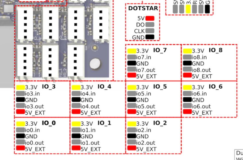
-
@nightowl999 said in Wiring a non-latching switch with LED:
I was going to use this io0.in and .out, and I'm pretty sure @burtonenator is using a MB6HC and it worked for him.
Couldn't see for looking.
That should be fine then. -
@owend
Whew! Thank you -
I need to extend this question a bit...
The external switch I'm using to activate the pause.g and resume.g macros during a projectworks really well, even turning on/off the LED within the switch - thank you @burtonenator!
But the LED in the switch is 12V, so I sourced some 5V white LEDs to replace it, but that's pretty dim too, so I'm guessing the 5V supply at the io_n pins doesn't provide much in the way of current to drive the LED, which is fair enough.
The momentary switch is connected across the io0.in and GND, and the LED across the io0.out and 5V.
As an alternative, I was thinking of reverting back to a 12V LED and use one of the Out4-6 headers instead. The current (haha) configuration is this:
; Extract from config.g
M950 P8 C"!io0.out"				; create output/server port 8 on inverse io0.out
global PausePress = false


; LED code in pause.g and resume.g files
M42 P8 S0					; pause/resume LED off
set global.PausePress = !global.PausePress	; toggle the value from whatever it was before


; trigger2.g
echo "called at " ^ state.time
G4 S1						; delay 10ms to debounce
if sensors.gpIn[9].value=1
	echo "debounce"
	M99 					; break out if sensor value is zero again (bouncing)
if job.file.fileName !=null			; if there's a job filename then it's reasonably safe to say we are printing
if global.PausePress == false			; the button hasn't been pressed so we'll pause
	echo "Pause"
	M25					; pause the current toolpath
else
	echo "Resume"				; resume the current toolpath
	M24
Assuming it would be OK to power an LED from one of the Out4-6 headers in the first place (please tell me if it's not!), wouldn't it just be a case of supplying 12V from there to the LED?
Failing this, I could use a relay and an external 12V supply.
I'm still using the Duet3 MB6HC powered via a 24V PSU, with RR 3.4.1 firmware and DWC 3.4.1.
Thanks
-
 undefined Nightowl referenced this topic
-
@owend said in Wiring a non-latching switch with LED:
The Output pin you choose may or may not have the capacity to drive the LED(s) directly (depends on what you're connecting). Refer to the specifications and if necessary either run it off a fan output or supply an external power source to the LED which you can control with the I/O via a mosfet module or similar.
So I'm going to go down this route after all. I've ordered a batch of mosfet modules, due to arrive today, which will help me sort this out.
Looking at the connection diagram for this though, am I correct in thinking I could now ignore the io0 voltage pins and connect the MB6HC io0.out and GND pins to the VCC and GND pins on the mofset module (which means the io0.in and io0.out would share the same GND pin)...

...and still use this configuration code in the config.g file:; Pause LED M950 P8 C"!io0.out" ; create output/server port 8 on inverse io0.out...and this in the pause.g and resume.g files:
M42 P8 S0					; pause/resume LED off
set global.PausePress = !global.PausePress	; toggle the value from whatever it was before
Connecting the supply and outputs from the module are straightforward, thankfully!
Thank you
Few things are more dangerous than taking the advice of someone who thinks he knows what he's doing.
I'm still on my learning curve, so take everything I say with caution!RatRig 1075, Duet3 MB6HC, Sorotec SFM 1000 PV-ER milling motor, Hobbyist
-
@nightowl999
No, looking at that layout you will use the 3.3v to VCC and GND to GND
io0.out to signal.
VIN is your external power source. -
@nightowl999
I don't have a duet3 but there are a number of higher output options on them.
OUT3-OUT7
They also support 12v internally and external voltages by jumper selection.
I suggest you read the docs on fan configuration and using a fan header as a gpio.
You may not need a mosfet module -
Thank you @owend
I'm going to use the mosfet just to switch the power to the LED on and off, and I understand the VIN/GND and V+/V- connectivity.
What I didn't understand is the way to connect the mosfet to the i/o port on the MB6HC, but you've made that clear, but I'd like to understand something...
In an earlier post, it was suggested I could connect the io0.in and GND for the switch and (possibly) io0.out and 5V for the LED. As I'm now using an external, independant power supply for the LED, is it because the mosfet needs the 3.3V/5V to power it?
I'd assumed (wrongly, it seems) the io0.out and GND would work to activate the external 'switch' within the mosfet, in reverse to the way the external switch activates the MB6HC's 'switch' io0.in and GND, and why I was asking if I could use the same GND.
I'm using 5V LEDs, so the using OUT3-7 isn't an option, but I do have fans configured from OUT7 - I try not to be lazy and look this stuff up first, but it's not always written for the technically challenged user, to be honest!
-
@nightowl999
The mosfet module is essentially another plc (as opposed to a mosfet which is a single component)
It requires power for the logic circuit and a signal to tell it when to open/close the gate. -
undefined Nightowl referenced this topic