Mesh Bed Compensation Capabilities
-
Hi all,
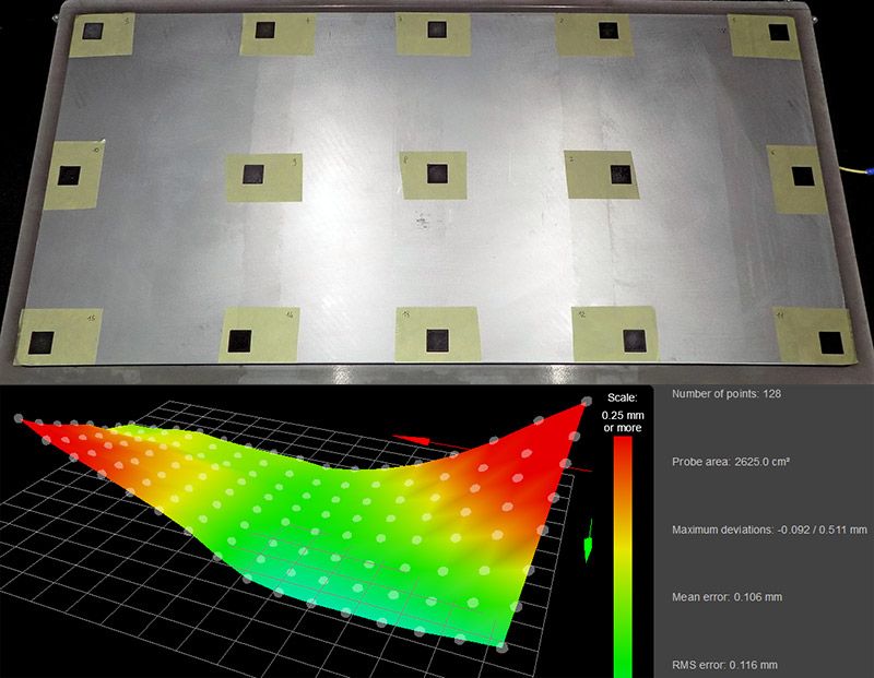
the attached image show single layer (0,2 mm) 20x20 mm rectangles printed on the the 800x400mm bed (at 50 °C) of my custom printer, with the heightmap created using a BLtouch and these M558 settings:M558 P9 F100 H3 R0.3 T10000 B0 A5 S0.03The bed show a non-negligible deviation from flatness and I noticed that:
-
Printing each rectangle one at a time, using a simple 2x2 probing grid for each of them, I'm able to obtain a perfect first layer for each of them.
-
Printing all the rectangles in the same session, also using a 400+ points grid on the entire plane, the rectangles situated in the areas that most deviate from flatness are printed very bad (ex. 0,35 mm thickness instead of the nominal 0,2 mm.)
So, I wonder about the true capabilities of the Mesh Bed Compensation function.
What am I missing? Am I asking too much from G29?Obviously when printing on a full large bed surface, despite using 400+ probe points, you will never able to abtain the same points density of probing with a 3x3 grid an 20x20 mm area, but… the deviation of flatness of a 20x20mm area are not so significant (imho, for a rectified aluminium plate) to disallow a good print also with a single probe point at the center of each 20x20mm area.
So I'm just wondering that the Mesh Bed Compensation function is not truly suited for very large print surface, maybe due to the math used in order to process the probe points information, but I will glad to listen to your opinions and experiences!
Thank you!
P.S. I'm using RepRapFirmware for Duet 2 WiFi/Ethernet 2.05 (2019-12-13b1) on Duet Ethernet 1.02 or later + DueX2
-
-
That twist shape makes it seem like your gantry has some skew more so than the bed.
can you test the probe trigger height at those marked locations on your bed? Set Z0 with G92 Z0 when the nozzle is touching the bed in those spots and use G30 S-1 to get the trigger height. Is it consistent across the bed surface? If not, there is some twist or skew causing the probe to tilt resulting it the trigger height varying across the XY plane. This isn't something that mesh compensation can account for because the mesh is being distorted by the printers physical geometry changing based on where the probe is. Mesh compensation can only create an accurate map if the probe offset remains constant.
Another way to test is to remove the probe from the equation entirely by setting the M558 probe type to P0 which will allow for manual probing. This will prompt you to jog the nozzle down to the bed surface whenever the probe is called. This eliminates any probe tilt and will give you a more accurate view of what the bed surface is like.
-
I agree that the issue is likely not the bed itself.
The first thing I would suspect is you have false probe-to-nozzle heights readings.
Here's a scenario that gives rise to this: Like phaedrux said, a slightly twisted X-linear rail causes x-axis tilt along its travel. This itself is not a problem, but if you have a probe position that is offset in Y (relative to the nozzle) it creates an error in height. In other words, probe gives a falsely low or high reading. For this reason I always position the probe with the minimal Y-offset. Ideally zero so unaffected by x-twist. Many printer designs ignore this important point.
-
Hi Phaedrux and bubblevisor and thank your for your kind replies!
Following you tips I've mapped the bed in cold and hot conditions, using BLTouch and manual probing. You will find the result in the attached image.
Yes, the manual probing procedure (jogging the nozzle down to the bed surface) is prone to non-negligible error, but it seems to me that we are able to exclude some kind of probe tilt: the warped surface trend emerges using both probing procedures, and warming the bed does nothing but emphasizing this trend.
What's your opinion about that?
Thank you!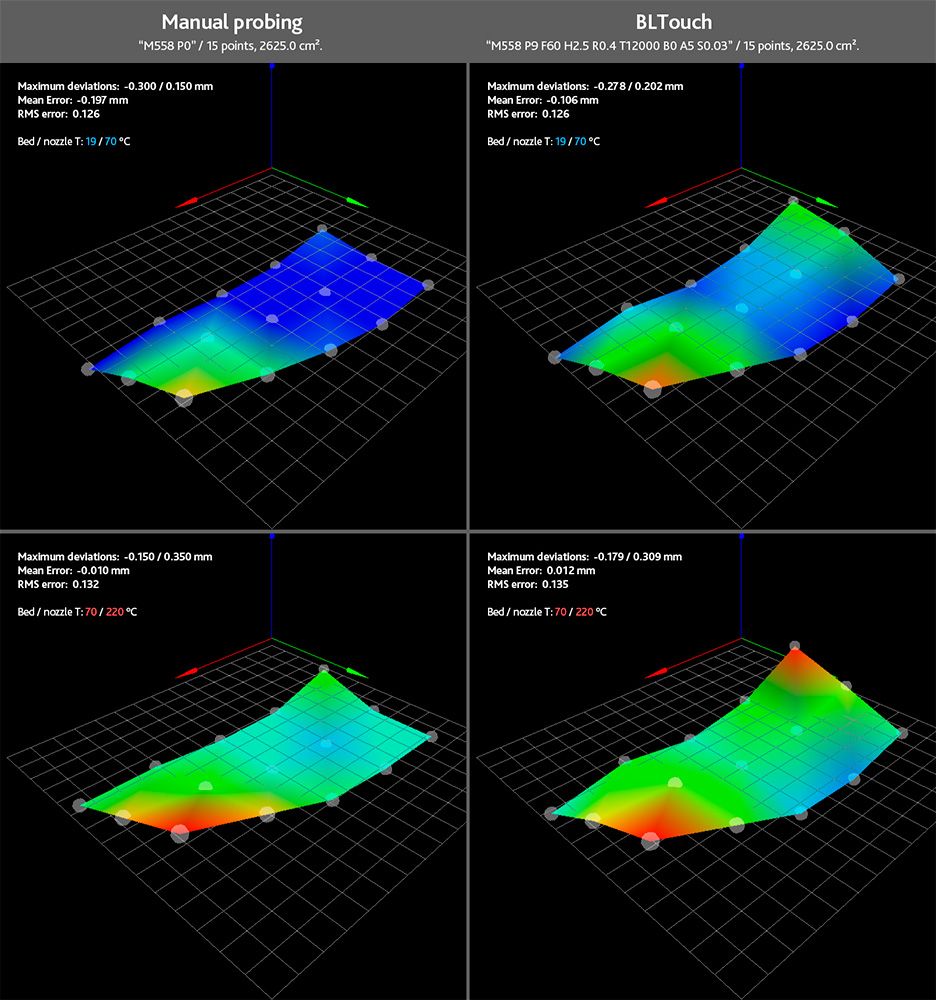
-
@3dreamer Counter check this model with a precise metal ruler and a light source over the diagonals of your bed: If these measures look similar to the warping you got from probing, the bed and/or its mounts are likely culprits. Else, you should have a closer look at the printer’s geometry and maybe the probe itself.
-
Do you have mesh taper set? If so, try disabling it.
https://docs.duet3d.com/User_manual/Reference/Gcodes#m376-set-bed-compensation-taper
-
@3Dreamer
Did you resolve your issue? I'm running into something similar... -
@tfjield said in Mesh Bed Compensation Capabilities:
@3Dreamer
Did you resolve your issue? I'm running into something similar...Unfortunately I've not totally resolved the issue.
I mean that the 99,9% of the users prints on small beds trusting on the intrinsic flatness of those surfaces, but when you print on big beds I think that you'll face a mix of problems:- It's difficult to get a truly flat surface across the entire plane, moreover when heating it at high temperatures.
- Obtaining an high-density probe map is truly time consuming.
- I suspect that the G29 algorithm is not truly capable to handle this kind of scenarios.
Maybe in the future we will use some LIDAR system to truly fast proble the entire bed at high resolution, etting an enhanced G29 algorithm truly do it's job. Ex. https://www.youtube.com/watch?v=vI_UiwHJeGI
A LIDAR system is yet used on the Bambu Lab X1 Series printers. -
I ended up getting my problems all sorted out. But I had to do several things:
- Increase the supports for my bed so that it was closer to level to start with. My bed is a bit over 600 mm x 600 mm and wasn't sufficiently supported, so there was a significant sag in the middle. Now I still have some sag, but my maximum variance across the surface is 0.387 mm.
- Fix the twist in my gantry. There was a couple degree twist along my y-axis, and due to the location of my BL Touch relative to my nozzle, just a degree resulted in a very significant height error. One degree of twist was over 0.4 mm of height error.
- I picked a common point on one corner for my z-axis datum, my probe z offset, my bed tilt probing points, and my bed mesh compensation.
- Performed a high resolution map (21 x 21) at temperature.
- Modified my macros so that for every print it will do the following:
o Verify that the axes have been homed. If not, home them.
o Verify that the bed has been adjusted for tilt. If not, adjust it, and home z again.
o Turn on bed mesh compensation.
I do not like the commonly accepted approach of using the center of the bed for my z datum. I work in a field where I'm very conscious of how things fail, and I don't want my datum at what is most likely the lowest point on my bed. If, for some reason, I don't turn on bed mesh compensation and I'm zeroed at that point, them I'm likely to run into my bed as I move away from the center and screw up my print head and PEI sheet. So I want my datum at one of the highest points.
Also, I want the corners of my bed tilt and bed mesh to be identical to my datum point, and use the same exact point for measuring the probe's z offset. In this way, it's easy for me to verify that everything is working right. My bed mesh should show zero compensation at that corner, and because I've already corrected the tilt, all four corners of the bed mesh should show almost zero compensation.
It's been a few weeks and several km of filament since I last took a bed mesh map, and my prints are rock-solid every time, now.