Duet3D Logo Duet3D
    • Tags
    • Documentation
    • Order
    • Register
    • Login
    1. Home
    2. 3Dreamer
    • Profile
    • Following 2
    • Followers 0
    • Topics 8
    • Posts 33
    • Best 7
    • Controversial 0
    • Groups 0

    3Dreamer

    @3Dreamer

    A strong background in the fields of Chemistry, 2D-3D Graphic Design and Electronics.

    9
    Reputation
    13
    Profile views
    33
    Posts
    0
    Followers
    2
    Following
    Joined Last Online
    Location Italy

    3Dreamer Unfollow Follow

    Best posts made by 3Dreamer

    • Vector printing (G2/G3/G5)

      Hi all,
      from some G2/G3 command tests conducted on my machine I noticed that vector printing produce smoother movements and material deposition, leading also to a better surface finish or permitting higher print speeds.

      G2/G3 Controlled Arc Move commands are already implemented in the firmware, so I'm here to ask you if there is the possibility to implement also the G5 command for Bézier curves interpretation.

      In my opinion it's a good idea to let the machine reach its real print resolution for curved movements, bypassing traditional G1 "pre-segmentation".

      Thank you!

      posted in Firmware wishlist
      3Dreamerundefined
      3Dreamer
    • RE: Mesh bed leveling - STL based probe points

      @engikeneer
      Hi all and thanks for your kind replies!

      I'm sorry, I didn't explain myself well: I've been using print-tailored probing grid for a long time, ex. using, in PrusaSlicer, the instruction:

      M557 X[first_layer_print_min_0]:[first_layer_print_max_0] Y[first_layer_print_min_1]:[first_layer_print_max_1] Px:y
      

      What I really meant is about probing points that follow the nozzle path of the first layer! While printing a ribbon-like spiral you will obtain, for example, a spiral probe map!

      posted in Firmware wishlist
      3Dreamerundefined
      3Dreamer
    • RE: Vector printing (G2/G3/G5)

      Thank you Bearer and Dougal1957 for your answers,

      @bearer said in Vector printing (G2/G3/G5):

      Are there slicers that output g-code that isn't segmented? I'm sure the firmware will evolve as we at some point move away from .stl as the intermediate step that remove all curves.

      Slicers are waiting for Firmwares and Firmwares are waiting for Slicers. Meanwhile FDM print software stagnate and machines are used well under their true capabilities.

      Anyway, Marlin firmware already support G5 commands (as experimental feature), while there are some pieces of software on GitHub that try to re-convert G1 movements into G2/G3 true arcs.

      Also consider that there are so much people that experiment with their printer and that do not alway use slicers to produce GCode. Sometimes I also use some self hand-coded softwares to generate the desired GCode commands.

      While we wait for overtaking STL it would be nice to let experimenters use their hardware at it's maximum capabilities 🙂

      @Dougal1957 said in Vector printing (G2/G3/G5):

      @bearer it is slated to be in KissSlicer V2 Premium in the very near future just as it will also support direct input of IGES and STEP Files

      Kiss

      As I know there is no guarantee that vector IGES/STEP informations will be translated into G2/G3/G5 instead of G1 commands, and I have very little hope by reading this page: http://www.kisslicer.com/premium-version.html

      Thank you!

      posted in Firmware wishlist
      3Dreamerundefined
      3Dreamer
    • RE: Vector printing (G2/G3/G5)

      @bearer Yes, it is clear, you are right.
      Anyway not everyone is an expert programmer, so I think it is legit to kindly ask/suggest for this kind of firmware additions, and this is the main goal of this thread.

      I hope that someone into Duet/RepRap firmware development will be able to listen to my suggestion, or point me towards some partial actual solution.

      Thank you!

      posted in Firmware wishlist
      3Dreamerundefined
      3Dreamer
    • RE: Vector printing (G2/G3/G5)

      Hi dc42,
      just checking to see if there's any news on G5 implementation 🙂

      Thank you!

      posted in Firmware wishlist
      3Dreamerundefined
      3Dreamer
    • RE: Mesh bed leveling - STL based probe points

      @infiniteloop said in Mesh bed leveling - STL based probe points:

      Of course, we have to make sure that the bed is levelled properly before we apply the mesh - it’s a misuse to take the grid as a means to get rid of levelling the bed.

      Sometimes, while the bed is properly levelled, there are still local roughness that can't be properly mapped by a grid, so why G29 can't it mov adapt the Z height in those points?
      Imagine printing on substrates like wooden boards, fabrics, wavy surfaces, eg.

      posted in Firmware wishlist
      3Dreamerundefined
      3Dreamer
    • RE: Vector printing (G2/G3/G5)

      Hi @dc42,
      is there any chance to see "G5 Bezier curves" implementation in the forthcoming period?
      We are almost ready with our experimental slicing software, so it would be nice to test it on our machine ,-)

      Thanks you so much for your work!

      posted in Firmware wishlist
      3Dreamerundefined
      3Dreamer

    Latest posts made by 3Dreamer

    • RE: LIDAR Bed Leveling

      @alankilian said in LIDAR Bed Leveling:

      @3Dreamer The sensor being discussed is not a LIDAR sensor, it's a LASER triangulation sensor, so it's nothing special technology-wise.

      People use triangulation sensors for bed leveling all the time and it has it's good and bad points.

      Hi alankilian,
      you are right. I'll quote a paper in order to introduce readers to the differences:

      3D ranging technologies generally fall into either position-based (triangulation) or time-based (LIDAR) approaches. Triangulation can provide much higher precision at close to mid-range but degrades quickly with the square of distance. LIDARs can provide reasonable precision over much longer distances but, unlike triangulation, they do not improve in capabilities at short range where precision and speed are critical for many applications such as autonomous rendezvous and docking, guidance and navigation, obstacle avoidance, and inspection.

      So let's us speak about those technologies!

      posted in 3D Printing General Chat
      3Dreamerundefined
      3Dreamer
    • RE: LIDAR Bed Leveling

      @dc42 said in LIDAR Bed Leveling:

      @3Dreamer last time I looked, the resolution and repeatability of LIDAR sensors was nowhere near good enough for 3D printer Z probing. However, the one you linked to claims repeatability down to 1um, so maybe the technology has improved enough now. How much does that one cost?

      Hi dc42,
      you can find some prices here: https://www.micro-epsilon-shop.com/de/wegsensoren/laser-wegsensoren/
      For sure this sensors cost as a good, small desktop printers, anyway this prices would be not a problem while considering high end machines (eg. > 5k)

      Here you can find some specs., especially for "Resolution /
      Repeatability" and "typeof reflection": https://www.luchsinger.it/contents/products/catalogo-sensori-laser-optoncdt-1.pdf

      @mrehorstdmd said in LIDAR Bed Leveling:

      @3Dreamer Who would ever have imagined that people would go to such lengths to avoid using a flat bed plate in a printer?

      I understand you! Anyway a lot of people are happy with their first layer printing results, also when prone to macro arctifacts that finally will not ruin ordinary prints.

      But pro users and researchers often needs to push the limits of the (FDM) technology. Have you ever tried to 3D print a thin (eg. 0.1 mm), single pass trace pattern all over a 1000x1000 mm aluminium grinded plane? You will need about 2500 probing points (a quantity not manageable by RRF2, without considering probing time!) to achieve a bare decent bed heightmap and I can assure you that this map will not be able to let you mantaining the desired nozzle-bed distance over the entire surface.

      posted in 3D Printing General Chat
      3Dreamerundefined
      3Dreamer
    • LIDAR Bed Leveling

      Hi all,
      just wondering if someone has experimented the use of LIDAR systems with Duet boards and RRF3.

      I'm thinking about are some compact and relatively cheap LIDAR sensors that you can actually buy (eg. https://www.micro-epsilon.com/displacement-position-sensors/laser-sensor/optoNCDT_1320/ ) in order to avoid the use of standard touch probe.
      A LIDAR will ideally led to fast obtain a truly detailed map of the bed surface or other surfaces (eg. if you want to print on an object.)

      I know that the "Bambu Lab X1" yet integrate a LIDAR system, anyway it seems that it finally rely on a classic touch probe:

      *The X1 uses a sophisticated dual-bed leveling system that makes use of two different sensors as well as an algorithm in order to try and nail the bed leveling. The first sensor is a lidar. According to Bambu Lab, it probes the nozzle height, assists with the first layer, and calibrates the flow of filament too. It will scan the bed before printing and has an accuracy of 7 microns.

      Following this, the scan is crosschecked with information from an analog probe, which looks like a standard touch probe you’ll find on many budget 3D printers’ automatic bed leveling systems. Working together, the two sensors should provide users with an effortless, accurate bed leveling system and, in combination with the AI, detect any errors happening early on in the first layer.*

      Thank you!

      posted in 3D Printing General Chat lidar bed leveling probe mapping heightmap
      3Dreamerundefined
      3Dreamer
    • RE: Mesh Bed Compensation Capabilities

      @tfjield said in Mesh Bed Compensation Capabilities:

      @3Dreamer
      Did you resolve your issue? I'm running into something similar...

      Unfortunately I've not totally resolved the issue.
      I mean that the 99,9% of the users prints on small beds trusting on the intrinsic flatness of those surfaces, but when you print on big beds I think that you'll face a mix of problems:

      • It's difficult to get a truly flat surface across the entire plane, moreover when heating it at high temperatures.
      • Obtaining an high-density probe map is truly time consuming.
      • I suspect that the G29 algorithm is not truly capable to handle this kind of scenarios.

      Maybe in the future we will use some LIDAR system to truly fast proble the entire bed at high resolution, etting an enhanced G29 algorithm truly do it's job. Ex. https://www.youtube.com/watch?v=vI_UiwHJeGI
      A LIDAR system is yet used on the Bambu Lab X1 Series printers.

      posted in General Discussion
      3Dreamerundefined
      3Dreamer
    • RE: Mesh Bed Compensation Capabilities

      Hi Phaedrux and bubblevisor and thank your for your kind replies!

      Following you tips I've mapped the bed in cold and hot conditions, using BLTouch and manual probing. You will find the result in the attached image.

      Yes, the manual probing procedure (jogging the nozzle down to the bed surface) is prone to non-negligible error, but it seems to me that we are able to exclude some kind of probe tilt: the warped surface trend emerges using both probing procedures, and warming the bed does nothing but emphasizing this trend.

      What's your opinion about that?
      Thank you!

      probe-test.jpg

      posted in General Discussion
      3Dreamerundefined
      3Dreamer
    • Mesh Bed Compensation Capabilities

      Hi all,
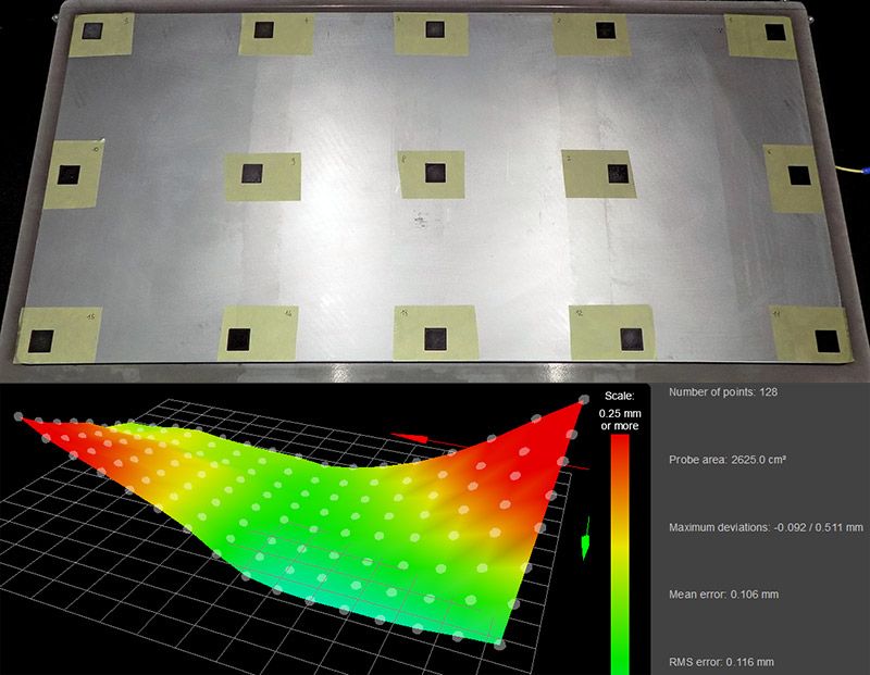
      the attached image show single layer (0,2 mm) 20x20 mm rectangles printed on the the 800x400mm bed (at 50 °C) of my custom printer, with the heightmap created using a BLtouch and these M558 settings:

      M558 P9 F100 H3 R0.3 T10000 B0 A5 S0.03
      

      The bed show a non-negligible deviation from flatness and I noticed that:

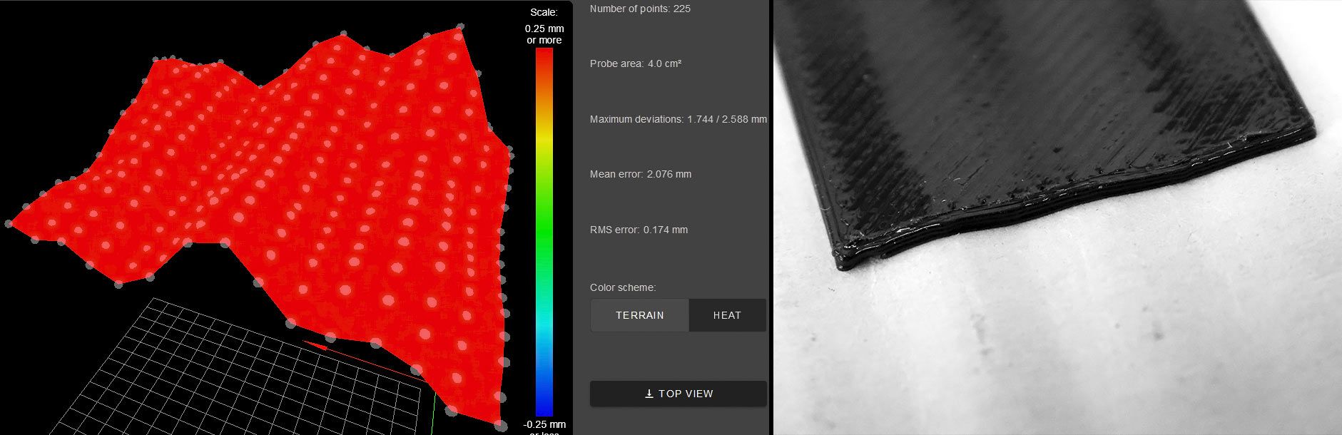
      • Printing each rectangle one at a time, using a simple 2x2 probing grid for each of them, I'm able to obtain a perfect first layer for each of them.

      • Printing all the rectangles in the same session, also using a 400+ points grid on the entire plane, the rectangles situated in the areas that most deviate from flatness are printed very bad (ex. 0,35 mm thickness instead of the nominal 0,2 mm.)

      So, I wonder about the true capabilities of the Mesh Bed Compensation function.
      What am I missing? Am I asking too much from G29?

      Obviously when printing on a full large bed surface, despite using 400+ probe points, you will never able to abtain the same points density of probing with a 3x3 grid an 20x20 mm area, but… the deviation of flatness of a 20x20mm area are not so significant (imho, for a rectified aluminium plate) to disallow a good print also with a single probe point at the center of each 20x20mm area.

      So I'm just wondering that the Mesh Bed Compensation function is not truly suited for very large print surface, maybe due to the math used in order to process the probe points information, but I will glad to listen to your opinions and experiences!

      Thank you!

      P.S. I'm using RepRapFirmware for Duet 2 WiFi/Ethernet 2.05 (2019-12-13b1) on Duet Ethernet 1.02 or later + DueX2

      large-bed.jpg

      posted in General Discussion
      3Dreamerundefined
      3Dreamer
    • RE: Mesh bed leveling - STL based probe points

      The attached image show a small 20x20 mm TPU rectangle printed on the wavy surface of a cardboard, using a 225 point mesh grid.

      While printing I noticed the Z axis responding fast in order to follow the wavy surface, so I think that all the discussed matter should concerns only a firmware/math solutions.

      It's all about how to manage the probeb points, letting the Z axis work to maintain the correct nozzle-bed distance when the nozzle pass over the probeb point, freeing ourself from a mandatory rectangular grid!

      So, for example, while printing a thin lattice you will be able to:

      • Achieve an high density map just of the first-layer footprint;
      • Better follow the surface roughness thanks to a "surgical precision" probing, avoiding wasting probe points.

      wavy-surface.jpg

      posted in Firmware wishlist
      3Dreamerundefined
      3Dreamer
    • RE: Mesh bed leveling - STL based probe points

      @engikeneer said in Mesh bed leveling - STL based probe points:

      I guess then the first step would be to come up with a heightmap system that isn't based on a regular and rectangular grid.

      That's it! 😉

      @infiniteloop said in Mesh bed leveling - STL based probe points:

      That's definitely a task quite different from what our printers are supposed to do. Something like terrain following? Interesting concept, but to do it right, you have to measure Z in situ, i.e. while printing. This should well be possible with the Duet (and a proper sensor), the real question is: how do you tell your slicer? Wavy surfaces are a concept he doesn't understand.

      Yes, true terrain following!
      Isn't that what G29 is supposed to do, after all?

      You would also map the surface with a laser or a sort of little odometer, mapping the entire print surface or just the path (G1 instructions) of the first layer, obviously with precision electronic due to sampling needs.

      Slicers? Where we're going, we don't need slicers.
      Apart from funny quotes, ideally the slicer should stay in the dark about what will happen during print process, because the firmware itself will take care of adjusting the Z position while printing.

      This discussion is intriguing 😉

      posted in Firmware wishlist
      3Dreamerundefined
      3Dreamer
    • RE: Mesh bed leveling - STL based probe points

      @infiniteloop said in Mesh bed leveling - STL based probe points:

      Of course, we have to make sure that the bed is levelled properly before we apply the mesh - it’s a misuse to take the grid as a means to get rid of levelling the bed.

      Sometimes, while the bed is properly levelled, there are still local roughness that can't be properly mapped by a grid, so why G29 can't it mov adapt the Z height in those points?
      Imagine printing on substrates like wooden boards, fabrics, wavy surfaces, eg.

      posted in Firmware wishlist
      3Dreamerundefined
      3Dreamer
    • RE: Mesh bed leveling - STL based probe points

      @engikeneer
      Hi all and thanks for your kind replies!

      I'm sorry, I didn't explain myself well: I've been using print-tailored probing grid for a long time, ex. using, in PrusaSlicer, the instruction:

      M557 X[first_layer_print_min_0]:[first_layer_print_max_0] Y[first_layer_print_min_1]:[first_layer_print_max_1] Px:y
      

      What I really meant is about probing points that follow the nozzle path of the first layer! While printing a ribbon-like spiral you will obtain, for example, a spiral probe map!

      posted in Firmware wishlist
      3Dreamerundefined
      3Dreamer