Unknown Print Error
-
@visionary If it is a temperature problem, what is the best temperature for PLA (for bed and nozzle) and if it is a extrusion issue, how do I fix it?
-
@kr15_uk Bed is really level, less that 0.025mm deviations
-
215 C (or 200-220 C) for hotend and 50 C (or 0- 60 C) for bed, but those may vary depending on exact position of thermistors (sometimes thermistor doesn't make the best possible contact to what it is suppose to measure). If your bed's actual temperature is higher than about 60 C the PLA will be very soft that should be usually avoided. Wrong parameters in your printers config/software can cause your printer to show and use incorrect temperature values.
3D-printer part collector || https://grabcad.com/eetu-4/models
-
@visionary And how would I know if it is an extrusion issue?
-
It might be hard to see from the print. One thing that can resolve overextrusion issues is to recalibrate E-steps.
Tip: Use these guides to determine printing quality issues:
https://www.simplify3d.com/support/print-quality-troubleshooting/
https://all3dp.com/2/3d-print-quality-12-tips-on-how-to-improve-it/ -
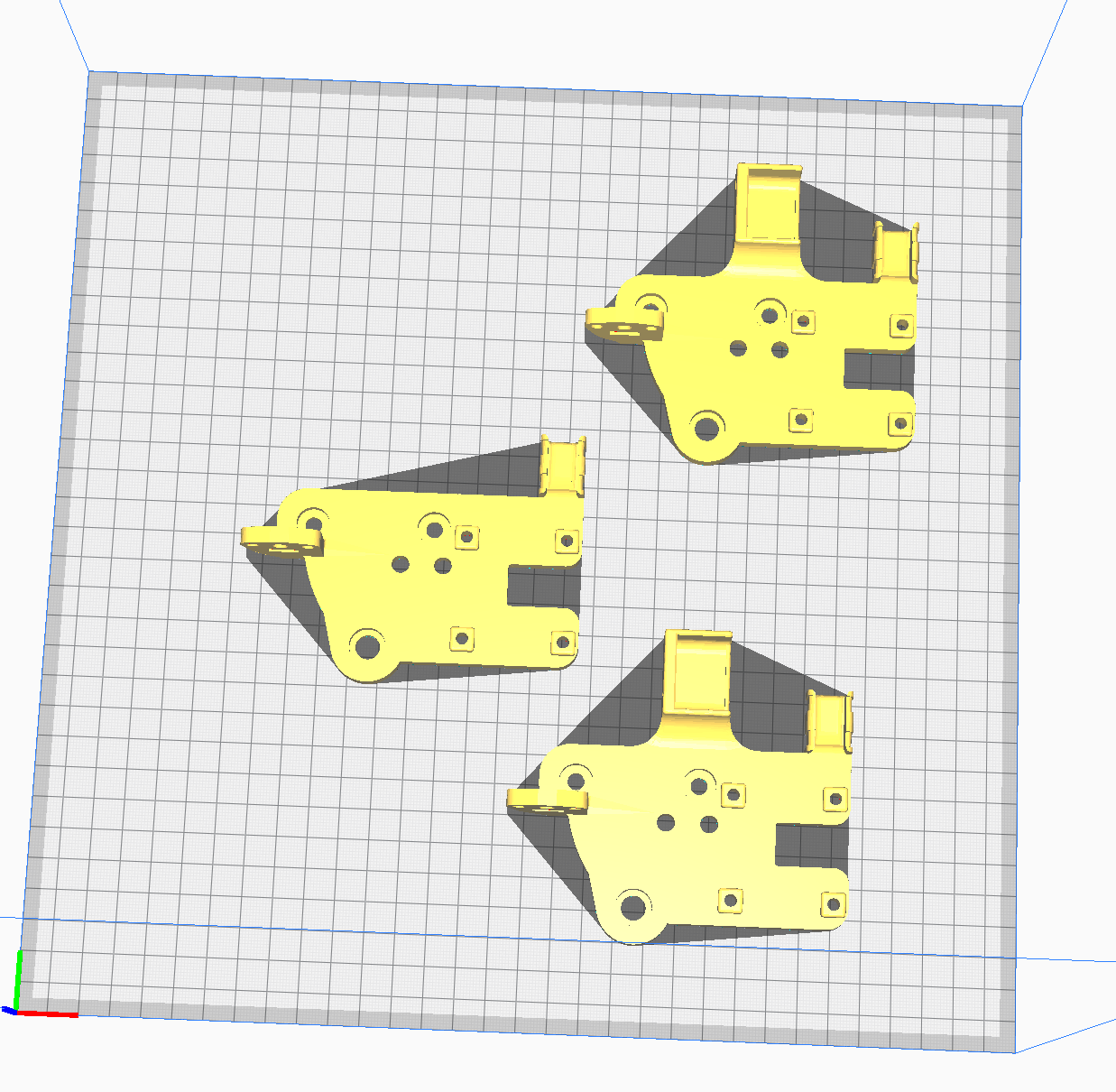
@tratoon can you post a screenshot of a stl itself, could help better understand what it’s suppose to look like
-
-
Some comments -
Setting z-offset. I'm and engineer and don't like the "paper test" because it assumes the sheet of paper is "some thickness" and that all pieces of paper are the same thickness, and that the edges don't get bent or get contaminated by a bit of hot plastic. I think a much better result is obtained by purchasing a set of "feeler gauges" something like this: https://www.amazon.com/Stainless-Feeler-Imperial-Measuring-0-02-1-00/dp/B08GLN7K1R. Get a long set, not the tiny ones for spark plugs. I set the Zoffset by heating up the bed and hot end, homing the printer (z axis is critical) and selecting the tool (send a T0 command if you have only one tool). Now, use the DWC move commands to bring the nozzle close to the bed, moving in small increments when you get close. Keep getting closer until the 0.2mm gauge slides in with a no (or maybe slight) dragging, and the 0.25mm gauge doesn't slide under (or needs to be shoved hard to fit). Now the nozzle is where you want Z=0.2 to be for this tool. The DWC will tell you what the current Z is for this tool. Then Send a
G10 P0 Z<some number> ; P0 means tool 0When you change the <some number>, notice that the Z in the DWC changes (note the nozzle does not move at this stage). Change <some number> until the Z in DWC says 0.2mm. This is the z offset you need and you can have confidence that a precision stainless steel gives you and that paper never will.
Add the G10 command to your config.g, or save it using an M500.
I always us the .2mm gauge because I always use a .2mm first layer, but you can really use any two gauges if they are flexible and there are two that are 0.05mm different in thickness.
But enough of my peeve and on to your core problem. If the parts are not being knocked off the bed (they look like they are not), then I think it's one of three things -
-
Belt slipping. if the error is always an offset of 2mm (or an increment of 2mm because that's the pitch of teeth on a GT2 belt), then it's almost certainly the belt jumping one tooth. Check the belt tension and also look for something hitting something during printing. With all the loose plastic in your pictures, small mis-print might have started a glop of plastic that hardened up and hit something.
-
Gear on stepper slipping on the shaft. If the shift is not an increment of 2mm, than one of two thing might be happening.
2A. If the little grub screw holding the gear to the stepper is not tight, when something hits something, the gear might be turning on the shaft rather than the belt slipping.
2B. A shift not in increments of 2mm can be the result of a motor skipping steps. This can be cause by a physical crash, a setting too high in acceleration or jerk, a sticky bearing, or maybe even a bad motor. You can try printing a single part and see if it fails at the same place every time, which implies something related to the specific gcode steps when the failure occurs.
Don't ask me how I learned about these possibilities...
-
-
@mikeabuilder The part fails at the same spot every single time. And also, I am assuming that you want a gap up 0.2mm for a 0.4mm nozzle, so what gap would you want for a 0.6mm nozzle. And also, do I just change <some number> to random numbers until I get 0.2 in the DWC?
-
Also what is the difference in using a G10 command rather than changing the Z-Offset in the G31 P500 X-41 Y-2 Z1.7 command? And if I were to use the G10 command, would I change the G31's offset to 0, then move the bed up until it touches the nozzle and set that as Z0, then move the bed down until the .2mm gauge fits properly and set the Z position in the DWC at that time as the <some number> in the G10? If this is not how I'm supposed to do it, would you mind explaining it in more depth?
-
@mikeabuilder on the paper vs feeler gauges topic. Paper weight is defined by its thickness, your typical office paper most likely is 80gsm which is 0.1 thick (if you have different gsm just Google for the chart) so double fold gives you 0.2. Paper “sponginess” can be advantageous really - when you drag your paper across it cleans your nozzle 1st to ensure you are measuring actual nozzle and not micro buildup and then you can simply feel the heigh (very useful if you can’t stick your face close to the bed). Also on the feel bit, it’s easier to feel 0.05mm difference with the paper than gauge, someone could easily stick 0.4 gauge in 0.2 gap and say feels ok, also with most machines and their borderline flimsy design you could manage to jam 0.6 and feel “ the same”. Something has to give and that’s rather paper sheet than printed part gantry (it’s your basic bushing argument really). Just to clarify - I’m not saying gauges are bad, no way, all I’m saying I wouldn’t dismiss sheet of paper that quickly hence for some, maybe even most, paper is better option.
-
@tratoon I’d go by 1st trying to print 1 item at the time or slowing print down, apart from not looking that pretty bottom bit of the part seems fine, it only fails when long travel is involved, could be as simple as your machine is not handling fast moves that well (current set too low or accelerations set too high)
-
@TRATOON - Setting the gap (with G10 or G31) is independent of the nozzle diameter. The goal is to get the machine set up so that when it is instructed to go to a particular Z value, the tip of the nozzle goes there precisely. The gap that is used for your first printed layer is set in the slicer.
G10 vs G31: G31 is about probing. It offset tells the firmware what height to set the machine coordinates to when the probe is triggered. If you type a G31 Z value in DWC, you need to probe Z again to have the new offset take effect. If you guess a bad value when trying to find the best one, you might crash the nozzle into the bed. But it is possible to leave the tool offset at 0 and just use the probe offset. I just find it is more work for me.
Should you set the G31offset to 0? If you do, you need to be sure your M208 minimum Z value is a negative number to allow the machine to move the nozzle closer to the bed than the probe point.
Here's my setup
In config.g, I haveM208 Z-4:250 ; other parameters left out for clarity M31 Z2.5 ; other parameters left out for clarityThe M208 sets the "soft" Z limit to -4, meaning the machine will never move farther that Z=-4 unless a command specifically says to ignore the limits.
The M31 says that the when the probe is triggered at Z=2.5.
In my homez,g file I have:
G30 ; I don't use other parameters here.And this says to move until the probe is triggered and set Z to the probe trigger height (2.5mm).
I never intentionally move Z to try to touch the nozzle to the bed. My method is to move to a specific distance (I picked .2mm) and test whether I've got it right with the feeler gauge. It's too hard to tell when "touching" the bed becomes "pushing into" the bed. AND I should be clear, all those "moving the nozzle" is done with DWC move commands, not moving the bed or nozzle with my hands. When I'm satisfied that I've got the nozzle set to .2mm above the bed, then I send G10 Z<some value> commands and see how they change the Z value displayed in DWC. and change until I get the displayed value to be 0.2mm.
-
@kr15_uk - I agree with you about paper being a pretty uniform thickness, but I always had problems with the paper getting mashed at the edge when the nozzle was a bit too close, or having a bit of plastic rub off the nozzle and worrying about the paper getting thicker. I did a lot of baby stepping on my first layers to dial things in. It left me frustrated, but lots of people use the paper method successfully every day. I guess everyone needs to get the feel for their method and once they do, they are good to go. AND I've gotten used to working with the feeler gauges.