32,4v input instead of 32v
-
The Duet3 6hc Mainbord needs 12-32v as power input.
Im looking forward to using a 36v industrial power supply which i can regulate down to 32,4v with the potentiometer.
What are the tolerances for power input on the mainboard? Will this nominal 2% too high voltage cause any harm?I couldnt find an answer in the shemetics.
Thanks in advance. -
@themcfly all components on the Duet 3 MB6HC are rated to at least 38V VIN max recommended and 40V absolute maximum. However, if you have a number of stepper motors connected running at high current and you turn them all off at once using M18, then they will dump power back into VIN, causing the VIN voltage to rise. It is to allow for some voltage rise that we recommend 32V maximum VIN. There are six 220uF capacitors on the 6HC to absorb this energy and limit the VIN rise.
If you know the inductance of your stepper motors then you can calculate the maximum voltage rise using this formula:
Vmax - sqrt(Vin^2 + n * (L/C)*I^2)
where L and C are the inductance per motor phase and the total capacitance across VIN, in Henrys and Farads, or millihenries and millifarads etc., I is the peak current per motor (as set by M906), and n is the number of motors.
Example: VIN = 32V, L = 4mH, C = 1.32 milliFarads (as on the 6HC), n = 6, I = 4A gives:
Vmax = sqrt(32^2 + 6 * (4/1.32) * 4^2) = 36.26V
You can do the sums with a VIN voltage greater than 32V and your own motors. If the voltage rise is unacceptable then you can connect additional capacitance between VIN and ground to reduce it.
-
@dc42 said in 32,4v input instead of 32v:
You can do the sums with a VIN voltage greater than 32V and your own motors. If the voltage rise is unacceptable then you can connect additional capacitance between VIN and ground to reduce it.
Is there any downside to adding extra capacitance? For sake of argument a 10F capacitor would make the voltage rise negligible:
sqrt(32^2 + 6 * (4/10000)*4^2) = 32.006Even with more reasonable capacitances I would guess inrush current and possibly safely bleeding the charge when needed would be important?
-
@nxt-1 a very high value capacitor might cause the PSU short circuit protection to kick in. However, something like 10000uF @ 50V should be suitable, and would also keep the motors energised for a little longer if there is a power failure, giving you a better chance of lifting the head off the print in the power fail script.
-
 undefined Nxt-1 referenced this topic
-
Info in this thread was very useful and allows to increase voltage for better performance of stepper motors. I use 350W 24V supply (for heaters) with additional (modified with higher output capacitance) Boost converter to get around 37V for Duet3 6HC. Everything works fine.
@dc42 said in 32,4v input instead of 32v:
all components on the Duet 3 MB6HC are rated to at least 38V VIN max recommended and 40V absolute maximum.
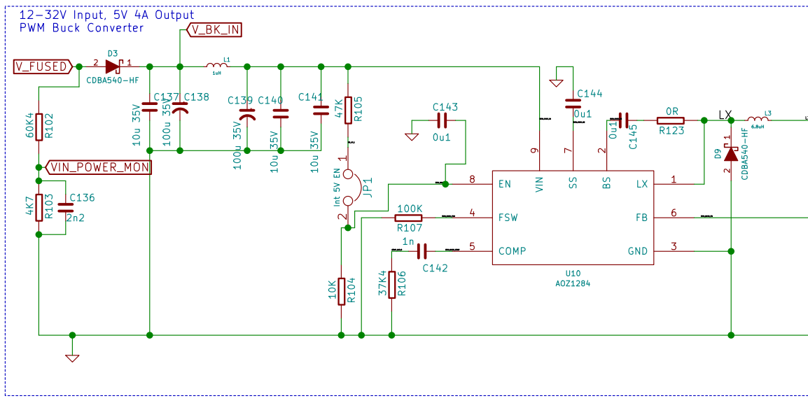
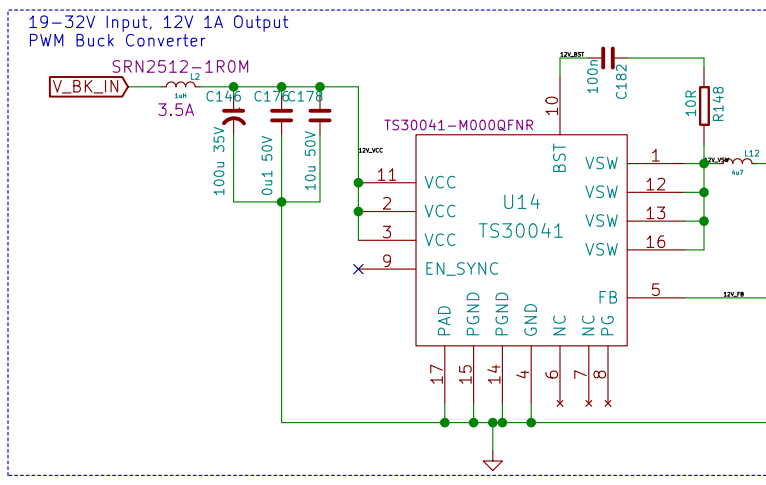
I was checking other stuff on schematics and found that input capacitors of DC-DC converters are rated 35V max. So even considering input protection diode D3 absolute max input voltage is 35,5V. Correct me if I am wrong.


Kind Regards,
-
@mandragora if you look at the capacitors on your 6HC you may find that they are rated 50V.
-
Thanks for info. 220uF caps for TMC's are marked 50V on schematic and their markings are "220 50A RN8" (I guess that 50 corresponds to 50V), but 100uF caps used for converters shown above are rated 35V on schematic. I could not decode actual markings of those caps marked "100 HFT 9B1" that are actually mounted on board, I've tried to find them on the web but I was unsuccessful. Also ceramic caps are never marked on its case, so it is impossible to confirm their voltage rating.
@dc42 said in 32,4v input instead of 32v:
@mandragora if you look at the capacitors on your 6HC you may find that they are rated 50V.
Does that mean that this schematic differs from actually mounted components? If yes, are there more changes in different parts of the design? I tried but didn't find any BOM to confirm what is actually mounted.
Kind Regards, -
@mandragora the H in the capacitor part number almost certainly means it is 50V. https://www.electronics-notes.com/articles/electronic_components/capacitors/capacitor-codes-markings.php. Also I've checked our internal BOM for the 6HC version 1.0 and those caps are specified as 100uF 50V.
We sometimes use higher-rated components than is shown on the schematic. Additionally we sometimes substitute similar parts for the ones shown on the schematic, due to the ongoing shortages of electronics components.
-
Thank you for clarification, I was concerned that I've overstressed capacitors which would lead to nasty failure.
Now I am relived
Kind Regards,
-
 undefined zapta referenced this topic
-
 undefined Mandragora referenced this topic