Setting up a pressure sensor with Duet3
-
Hello,
I would like to integrate a pressure transducer with my Duet3. It is a linear sensor that outputs from 0.5V (=0 psi) to 5V (=150psi) depending on the pressure it senses.
I believe that I would use a M308 S"sensor_number" P"pin_name" Y"linear-analog" Bnnn Cnnn command to set this up.
B is the value you want displayed at the ADC value = min and C is the value displayed at ADC value = max.
How would I know what the min and max ADC values are, and how that relates to the voltage output from the sensor? Where would I find out if the analog input pins are 5V tolerant or 3.3 V?
I was planning on connecting to either a temp pin or some other analog-enabled pin on the board.
Any help is appreciated.
Best,
Garth -
@garth_42 Hi, is there something I can do to make my issue more clear? I am not sure what the B and C values should be in order to get a value aligned with the PSI values from the sensor in the GUI. Also, I looked at the hardware overview and it says inputs are 30V tolerant, does this mean the input pin on any GPIO or SPI pin?
-
@garth_42 According to this IO table, IO 3 thru 7 support analog input.
I asked a similar question regarding a Z-probe-type device:
https://forum.duet3d.com/topic/29917/reading-analog-values-from-laser-range-finder-6hc/2My device also outputs 0-5v, so I will try one of those '5v to 3.3v logic level shifters.
The way I read the documentation for M308, it seems to me you can set B and C to 0 and 150 PSI. Someone else should check me on this, but i think RRF takes the input voltage (0-3.3v after level-shifting from 0-5v) and 'maps' that analog value to the B to C (0-150PSI) range of values. So when you query that sensor, you should get an output between 0-150, provided you're actually using the full range of the sensor.
Arduino has a funcction called map( ) that does this exactly.
-
@hebigt Thanks for the reply! This is great info, and the way that you are thinking it works makes logical sense to me, too, now that I have more information about it. Once I get around to making the connections, I will update if you haven't already posted about your setup working. I am surprised your post didn't come up in the searches I did on the forum.
-
@hebigt do check that the logic level shifter is actually going to send a scaled input of the 0-5V to 0-3.3V. Many of them will have a threshold and everything below the threshold will be output at logic 0, with everything above the threshold being output as logic 1.
You may be better off using a simple resistive divider circuit that scales 0V-5V to 0-3.3V. otherwise an amplifier circuit design to translate the analog signals linearly would be a good choice.
-
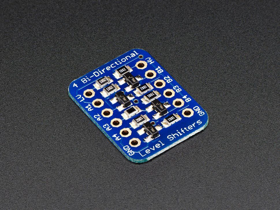
@t3p3tony Thank you for the tip! This is what I ordered, although I can't say for sure whether it scales the input like you described.
-
@hebigt unfortunately that level shifter is for logic signals only. I suggest you use two resistors, as @T3P3Tony suggested. For example, 2K4 between the sensor output and the Duet input, and 3K3 between the Duet input and ground. These values assume that the sensor is capable of sourcing at least 1mA of current.