External driver not working
-
Hi everyone,
I'm trying to convert a Creatbot D600 Pro to a Duet 3.
Why ? because its electronic is archaic, buggy, and impossible to modify (it's an old 9 bit board and they don't share their Marlin Configuration).How it was
In this big printer, the stepper motors are connected with external stepper drivers.
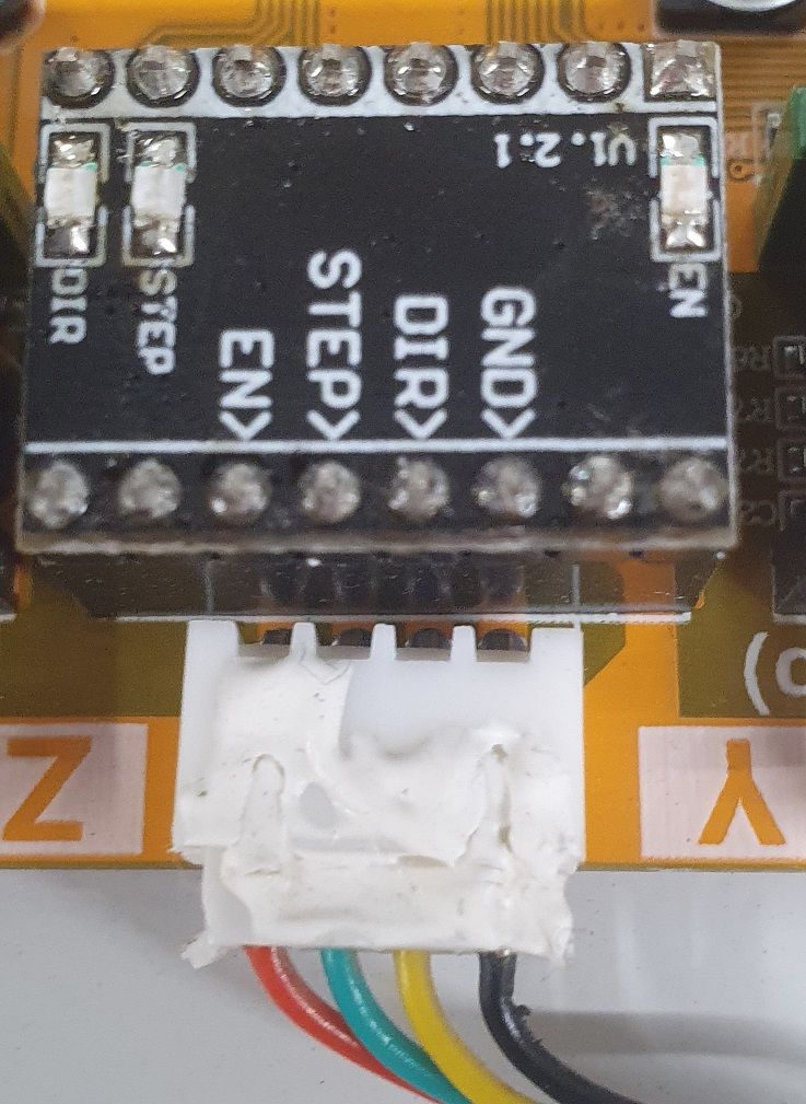
There are two drivers attached to the X and Y motors and one on the electronic panel for the Z stepper.These driver where connected to the original board with just 4 cables and a dummy stepstick stepper :
Photo 1
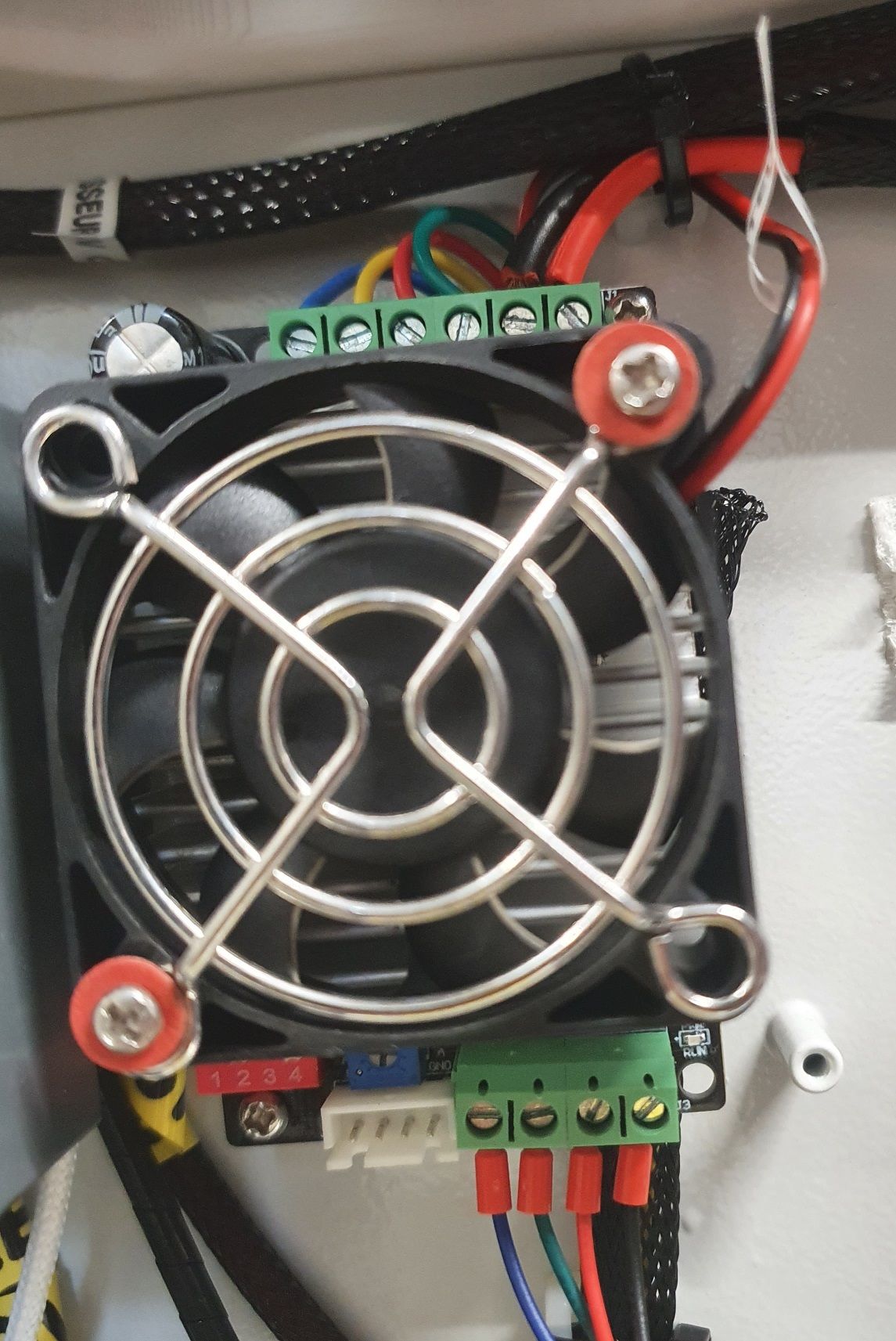
This is the Z external stepper driver, from this page, I believe it's a TB6600 :
Photo 2
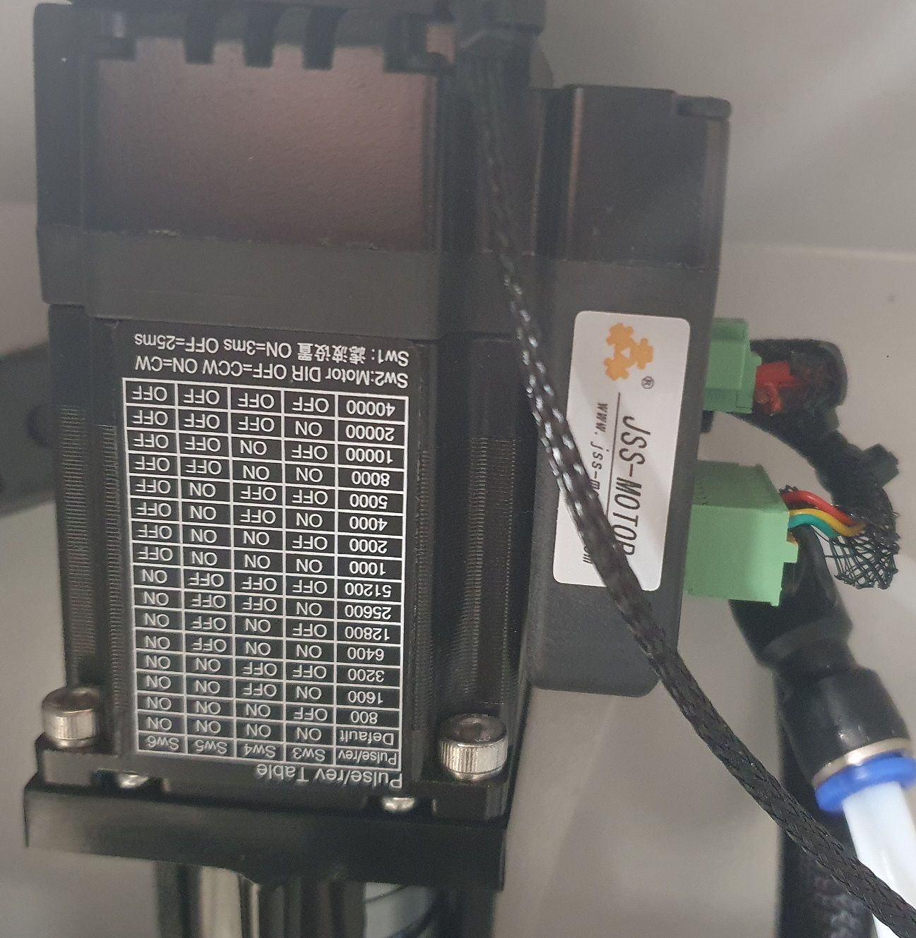
This is the X and Y external stepper driver (and stepper), which are advertised as closed loop stepper driver. I believe it is this reference
Photo 3
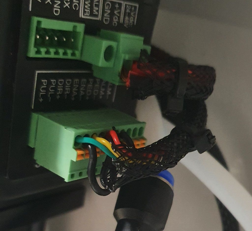
For the X and Y stepper driver, the (-) of PUL, DIR and EN are connected together and there are 3 cables for the (+) of PUL DIR and EN :
Photo 4
Well I'm having trouble to make these two stepper moves from the Duet boards that I installed.
When the printer still had its board, I was able to find the steps per mm for these axes :
X266.67 Y266.67 Z960.00 E392How it is
Here is what I'm doing. I bought a Duet 3 6HC.
( This wasn't my smartest move as all the motors are driven by external stepper driver and the extruder will be driven by a toolboard. I should have gone with the 6XD )
To use the external driver, i'm using three of the Duet3 Expansion 1XD.For Z, seeing as their was a GND, I assumed the other EN DIR and CLK where the positivs so I connected the four cables to the external stepper as such :
Photo 5
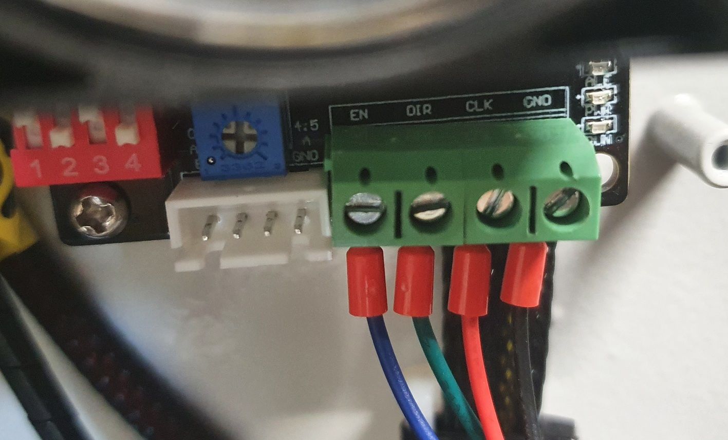
And I connected the other end of these cable to the 1XD expansion board as such :
Photo 5
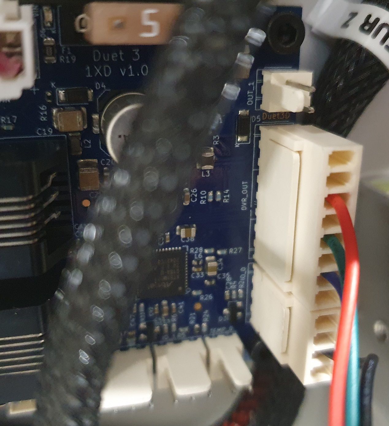
So
External stepper -> 1XD Board
CLK -> D0_STEP (+)
DIR -> D0_DIR (+)
EN -> D0_EN (+)
GND - > GND (on the IO0)
I also tried to connect the
GND - > D0_EN (-)For X and Y, seeing how the board was connected before, with all the ground (-) connected, and individual cables for PUL(+), DIR(+) and ENA(+).
I tried to connect it that way :
Photo 6
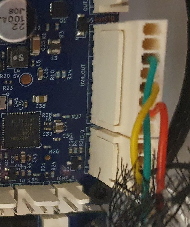
So the same way as for Z :
External stepper -> 1XD Board
CLK -> D0_STEP (+)
DIR -> D0_DIR (+)
EN -> D0_EN (+)
GND - > GND (on the IO0)
I also tried to connect the
GND - > D0_EN (-)Results : does not work. Stepper don't moves.
More information on the firmware side :
I have managed to connect to the 1XD board perfectly. I re-assigned their CAN adress and updated them following the recommendation from the documentation. They all communicate well when I send M122 B**. Their can adresses are 40 for X, 41 for Y and 42 for Z.
What I did to test if the motor worked was send a G92 X50 Y50 Z50 to artificially home the printer and then send command to move in X/Y/Z.
The position is changing on the web interface but nothing moves.Here is my config.g file :
; Configuration file for Duet 3 MB 6HC (firmware version 3.3) ; executed by the firmware on start-up ;######################## ; General preferences ;######################## M111 S0 ; Debugging off G21 ; Work in millimetres G90 ; Send absolute coordinates... M83 ; ...but relative extruder moves M555 P2 ; Set firmware compatibility to look like Marlin M667 S1 ; Select CoreXY mode ;######################## ; Network ;######################## M550 P"Creatbot" ; Set machine name M553 P*********** ; Ethernet Settings - Mask M554 P*********** ; Ethernet Settings - Passerelle M552 P*********** ; Ethernet Settings - Adresse M552 S1 ; Enable Networking M586 P0 S1 ; Enable HTTP M586 P1 S0 ; Disable FTP M586 P2 S0 ; Disable Telnet ; Wait a moment for the CAN expansion boards to start G4 S2 ;######################## ; Drive ;######################## ;Drive directions M569 P121 S1 ; Drive on Toolboard (E0) - change to 20 when toolboard installed M569 P40 R1 S0 ; Drive on 1XD (X) - I also tried R0 M569 P41 R1 S0 ; Drive on 1XD (Y) - I also tried R0 M569 P42 R1 S0 ; Drive on 1XD (Z) - I also tried R0 M569 P40 T2.7:2.7:2.7:2.7 M569 P41 T2.7:2.7:2.7:2.7 M569 P42 T2.7:2.7:2.7:2.7 ;Drive mapping and control M584 X40 Y41 Z42 E121 ; Stepper motor connection points - change E121 to E20 when toolboard installed M350 E16 I1 ; Configure microstepping with interpolation for the extruder M92 X266.67 Y266.67 Z960.00 E392 ; Set steps per mm assuming (I also tried to increase these value to 5000,5000,5000 to see if it was moving just a little bit because of too small values) ; Axis Limits M208 X0 Y0 Z0 S1 ; Set axis minima - need adjustments M208 X600 Y600 Z600 S0 ; Set axis maxima - need adjustments ;Drive speeds and acceleration M203 X18000 Y18000 Z600 E5000 ; Set maximum speeds (mm/min) M201 X1000.00 Y1000.00 Z100 E2500 ; Set maximum accelerations (mm/s^2) M566 X400 Y400 Z10 E400 ; Set the jerk : maximum instantaneous speed changes (mm/min) ; Motor current M906 E1000 I30 ; Set motor currents (mA) and motor idle factor to 30% M84 S30 ; Set idle timeout ;######################## ; Endstops ;######################## ; Axis Limits M208 X0 Y0 Z0 S1 ; Set axis minima M208 X500 Y500 Z499 S0 ; Set axis maxima ; Endstops M574 X1 S1 P"40.io1.in" ; Set endstop position (X), type (P) and connection point (P) - on 1XD for X (will probably need to change that so that the X endstop is connected to the toolboard ) M574 Y1 S1 P"41.io1.in" ; Set endstop position (Y), type (P) and connection point (P) - on 1XD for Y M574 Z1 S1 P"42.io1.in" ; Set endstop position (Z), type (P) and connection point (P) - on 1XD for Z (will probably need to change that because the Z endstop is a BLTouch) ; Z-Probe M950 S0 C"121.io0.out" ; Create servo pin 0 for BLTouch at connection point (C) M558 P9 C"121.io0.in" H5 F120 T6000 ; Set Z probe type to bltouch (P), the connection point (C), ; the dive height (H), the dive speeds (F), travel speed between probe points (T) G31 P500 X11 Y11 Z1 ; Set Z probe trigger value (P), offset (XY) and trigger height (Z) M557 X40:300 Y40:300 S40 ; define mesh grid ;######################## ; Heaters ;######################## ;Heated bed M308 S0 P"temp0" Y"thermistor" A"Bed" T100000 B3950 ; Set thermistor number (S), connection point (P), name (A) and parameters (YTBC) M950 H0 C"out0" T0 ; Set heater number (H), connection point (C) and map it to a sensor (T) M143 H0 S105 ; Set temperature limit M140 H0 ; Set this heater as bed heater ;Tool M308 S1 P"121.temp0" Y"thermistor" T100000 B4725 C7.06e-8 ; Set thermistor number (S), connection point (P), name (A) and parameters (YTBC) M950 H1 C"121.out0" T1 ; Set heater number (H), connection point (C) and map it to a sensor (T) M143 H1 S285 ; Set temperature limit ;Heated chamber M308 S2 P"temp1" Y"thermistor" T100000 B3950 ; Set thermistor number (S), connection point (P), name (A) and parameters (YTBC) M950 H2 C"out1" T2 ; Set heater number (H), connection point (C) and map it to a sensor (T) M143 H2 S80 ; Set temperature limit M141 H2 ; Set this heater as chamber heater ;######################## ; Fans ;######################## REPRENDS ICI !! ; Fans M950 F0 C"121.out2" Q500 ; create fan 0 on pin 121.out2 and set its frequency M106 P0 S0 H1 T50 ; set fan 0 value. Thermostatic control is turned on M950 F1 C"121.out1" Q500 ; create fan 1 on pin 121.out1 and set its frequency M106 P1 S0 H-1 ; set fan 1 value. Thermostatic control is turned off M950 F2 C"out4" Q500 ; create fan 2 on pin out4 and set its frequency M106 P2 S0 H-1 ; set fan 2 value. Thermostatic control is turned off ;######################## ; Tools ;######################## ; Tools M563 P0 S"Tool" D0 H1 F0:1 ; define tool 0 G10 P0 X0 Y0 Z0 ; set tool 0 axis offsets G10 P0 R0 S0 ; set initial tool 0 active and standby temperatures to 0C ;CONFIG NOT FINISHED ;######################## ; PID tune ;######################## ;######################## ; Pressure advance ;######################## ;######################## ; Others ;######################## T0 ; select first tool -
@fbunel I am running such external drives with duet2 and expansion board and it works. For duet 3 I believe they have a board without drivers
-
Would you not be able to connect those stepper motors directly to the drivers on the 6HC? Why still use the external drivers?
-
@Phaedrux
For the Z axis probably as it's a regular nema 23.
For the two others, these are closed loop driver with an encoder which I believe is not possible to drive from the duet 3.The thing is, it is still supposed to work and i had like to understand why it does not
-
@fbunel said in External driver not working:
External stepper -> 1XD Board
CLK -> D0_STEP (+)
DIR -> D0_DIR (+)
EN -> D0_EN (+)
GND - > GND (on the IO0)Try EN -> D0_EN (-) instead, because the enable inputs to stepsticks are active low.
-
@dc42
I just tried it for the X and Z stepper driver and it did not work.
External st epper -> 1XD Board
CLK -> D0_STEP (+)
DIR -> D0_DIR (+)
EN -> D0_EN (-)
GND - > GND (on the IO0)Also, I tried to connect the endstops to see if it was blocking something but it did not.
When I press home it does not move and just keep trying to move? -
@fbunel your M584 line in config.g is wrong:
M584 X40 Y41 Z42 E121
It should be:
M584 X40.0 Y41.0 Z42.0 E121.0
The same with your M569 commands, the P parameters should be P40.0, P121.0 etc. These are not numbers, they are board.driver identifiers, so the .0 is significant.
If you run M98 P"config.g" then these and perhaps other errors should be reported.
-
@dc42 THANK YOU. It works perfectly now. You're the boss.
-
 undefined Shoki referenced this topic