@dc42 I just tried it.
This did not make a difference for me.
The firmware was correctly installed and the name displayed on the Paneldue corresponds to the one you provided.
Best posts made by Shoki
-
RE: Duet 2 Ethernet disconnect when printing and paneldue connectedposted in PanelDue
-
RE: Tool and probe offset to variabneposted in Gcode meta commands
@T3P3Tony Thanks a lot ! I missed them when I read through the object model I don't know why.
-
RE: Heater fault not detectedposted in Using Duet Controllers
@gloomyandy @infiniteloop @jay_s_uk
I believe you were right and the problem was indeed a wiring problem.
With the printer on, I just jiggled the connector on the duet and the readings went off the charts. I believe it's just bad crimps and I will re-do these and it should fix the problem. I checked the cable themselves and they look fine.However, this still does not explain why the heater fault was not triggered at 8:46 with the huge temperature drop.
@infiniteloop Yes I made a typo, I typed "M570 H4" (which is my bed heater).
Since I haven't changed this in my config.g, it's the default value for all the heaters.
And this is my config.g :
; Configuration file for Duet WiFi / Ethernet running RRF3 on E3D Tool Changer ; executed by the firmware on start-up ;######################## ; General preferences ;######################## M111 S0 ; Debugging off G21 ; Work in millimetres G90 ; Send absolute coordinates... M83 ; ...but relative extruder moves M555 P2 ; Set firmware compatibility to look like Marlin M667 S1 ; Select CoreXY mode ;######################## ; Network ;######################## M550 P"ToolChanger" ; Set machine name "part of config.g deleted for obvious reasons" ;######################## ; Drive ;######################## ;Drive directions M569 P0 S0 ; Drive 0 (X) M569 P1 S0 ; Drive 1 (Y) M569 P2 S1 ; Drive 2 (Z) M569 P3 S0 ; Drive 3 (C) M569 P4 S0 ; Drive 4 (E0) M569 P5 S0 ; Drive 5 (E3) M569 P6 S0 ; Drive 6 (E2) M569 P7 S0 ; Drive 7 (E1) M569 P8 S0 ; Drive 8 UNUSED M569 P9 S0 ; Drive 9 UNUSED ;Drive mapping and control M584 X0 Y1 Z2 C3 E4:7:6:5 ; Stepper motor connection points, see C:\Users\YN14386\Documents\Documentation\Toolchanger for wiring diagram M208 X-35:328.5 Y-49:243 Z0:300 C-45:360 ; Set axis maxima & minima M92 X100 Y100 Z800 C91.022 E392:392:392:392 ; Set steps per mm assuming x16 microstepping M350 X16 Y16 Z16 I1 ; Configure microstepping with interpolation for the extruders M350 E16:16:16:16 I1 ; Configure microstepping with interpolation for the XYZ movements M350 C16 I10 ; Configure microstepping without interpolation for the coupler ;Drive speeds and acceleration M203 X35000 Y35000 Z1200 C5000 E5000:5000:5000:5000 ; Set maximum speeds (mm/min) M201 X2000 Y2000 Z400 C500 E2500:2500:2500:2500 ; Set maximum accelerations (mm/s^2) was X6000 Y6000 M566 X400 Y400 Z8 C2 E400:400:400:400 ; Set the jerk : maximum instantaneous speed changes (mm/min) ; Motor current M906 X1800 Y1800 Z1330 I30 ; Idle motion motors to 30% M906 E1000:1000:1000:1000 C500 I10 ; Idle extruder and cooupler motors to 10% ;######################## ; Endstops ;######################## ;X and Y axis M574 X1 Y1 S3 ; Set X / Y endstop stall detection M915 X Y S3 F0 H400 R1 ; Stall Detection for the X and Y Axes ; ; Coupler Axis M574 C0 Z0 ; No C Z endstop, it just crashes ;Z axis M558 P8 C"zstop" H3 F360 I0 T20000 ; Set Z probe type to switch, the axes for which it is used and the dive height + speeds G31 P200 X0 Y0 Z0 ; Set Z probe trigger value, offset and trigger height M557 X10:290 Y20:180 S40 ; Define mesh grid ;M376 H15 ; bed compensation taper ;######################## ; Heaters ;######################## ;see C:\Users\YN14386\Documents\Documentation\Toolchanger\*** for connection points names ;Tool 0 M308 S0 P"e1temp" Y"thermistor" A"Heater 0" T100000 B4725 C7.06e-8 ; Set thermistor number (S), connection point (P), name (A) and parameters (YTBC) M950 H0 C"e1heat" T0 ; Set heater number (H) and connection point (C) M143 H0 S285 ; Set temperature limit for heater to 285C ;Tool 1 M308 S1 P"duex.e2temp" Y"thermistor" A"Heater 1" T100000 B4725 C7.06e-8 ; Set thermistor number (S), connection point (P), name (A) and parameters (YTBC) M950 H1 C"duex.e2heat" T1 ; Set heater number (H) and connection point (C) M143 H1 S285 ; Set temperature limit for heater to 285C ;Tool 2 M308 S2 P"duex.e3temp" Y"thermistor" A"Heater 2" T100000 B4725 C7.06e-8 ; Set thermistor number (S), connection point (P), name (A) and parameters (YTBC) M950 H2 C"duex.e3heat" T2 ; Set heater number (H) and connection point (C) M143 H2 S285 ; Set temperature limit for heater to 285C ;Tool 3 M308 S3 P"duex.e4temp" Y"thermistor" A"Heater 3" T100000 B4725 C7.06e-8 ; Set thermistor number (S), connection point (P), name (A) and parameters (YTBC) M950 H3 C"duex.e4heat" T3 ; Set heater number (H) and connection point (C) M143 H3 S285 ; Set temperature limit for heater to 285C ;Heated bed M308 S4 P"bedtemp" Y"thermistor" A"Bed" T100000 B4138 C0 ; Set thermistor number (S), connection point (P), name (A) and parameters (YTBC) M950 H4 C"bedheat" T4 ; Set heater number (H) and connection point (C) M143 H4 S110 ; Set temperature limit for bed heater to 110C M140 H4 ; Bed heater is heater 4 ;######################## ; Fans ;######################## ;Tool 0 M950 F4 C"fan1" ; Set hotend fan number (F) and connection point (C) M106 P4 S255 H0 T60 ; Link fan to Heater (H) and turn it for temperature above 60C (T) M950 F0 C"fan2" ; Part cooling fan connection point M106 P0 S0 ; Turn off the part cooling fan. ;Tool 1 M950 F5 C"duex.fan3" ; Set hotend fan number (F) and connection point (C) M106 P5 S255 H1 T60 ; Link fan to Heater (H) and turn it for temperature above 60C (T) M950 F1 C"duex.fan4" ; Part cooling fan connection point M106 P1 S0 ; Turn off the part cooling fan. ;Tool 2 M950 F6 C"duex.fan5" ; Set hotend fan number (F) and connection point (C) M106 P6 S255 H2 T60 ; Link fan to Heater (H) and turn it for temperature above 60C (T) M950 F2 C"duex.fan6" ; Part cooling fan connection point M106 P2 S0 ; Turn off the part cooling fan. ;Tool 3 M950 F7 C"duex.fan7" ; Set hotend fan number (F) and connection point (C) M106 P7 S255 H3 T60 ; Link fan to Heater (H) and turn it for temperature above 60C (T) M950 F3 C"duex.fan8" ; Part cooling fan connection point M106 P3 S0 ; Turn off the part cooling fan. ;######################## ; Tools ;######################## ;Tool 0 M563 P0 S"Tool 0" D0 H0 F0 ; Define the tool : its number (P), its name (S), its extruder drive (D), its heater (H) and its part cooling fan (F) G10 P0 X0 Y0 Z0 ; Reset tool axis offsets G10 P0 R0 S0 ; Reset initial tool active and standby temperatures to 0C ;Tool 1 M563 P1 S"Tool 1" D1 H1 F1 ; Define the tool : its number (P), its name (S), its extruder drive (D), its heater (H) and its part cooling fan (F) G10 P1 X0 Y0 Z0 ; Reset tool axis offsets G10 P1 R0 S0 ; Reset initial tool active and standby temperatures to 0C ;Tool 2 M563 P2 S"Tool 2" D2 H2 F2 ; Define the tool : its number (P), its name (S), its extruder drive (D), its heater (H) and its part cooling fan (F) G10 P2 X0 Y0 Z0 ; Reset tool axis offsets G10 P2 R0 S0 ; Reset initial tool active and standby temperatures to 0C ;Tool 3 M563 P3 S"Tool 3" D3 H3 F3 ; Define the tool : its number (P), its name (S), its extruder drive (D), its heater (H) and its part cooling fan (F) G10 P3 X0 Y0 Z0 ; Reset tool axis offsets G10 P3 R0 S0 ; Reset initial tool active and standby temperatures to 0C ;######################## ; PID tune ;######################## ; run M303 T0 S230 with the tool you want to autotune (T) and the target temperature (S) ; for the bed, run M303 H4 S80 with the target temperature (S) ;Tool 0 M307 H0 R2.020 K0.305:0.329 D5.69 E1.35 S1.00 B0 V24.2 ;PID parameter for a heater (H) ;Tool 1 M307 H1 R1.887 K0.290:0.268 D6.00 E1.35 S1.00 B0 V24.3 ;PID parameter for a heater (H) ;Tool 2 M307 H2 R1.854 K0.286:0.300 D6.01 E1.35 S1.00 B0 V24.3 ;PID parameter for a heater (H) ;Tool 3 M307 H3 R1.973 K0.430:0.139 D6.19 E1.35 S1.00 B0 V24.3 ;PID parameter for a heater (H) ;Bed M307 H4 R1.223 K0.255:0.000 D3.83 E1.35 S1.00 B0 ;PID parameter for the bed heater (H) ;######################## ; tool offsets ;######################## ; !ESTIMATED! offsets for: ; V6-tool: X-9 Y39 Z-5 ; Volcano-tool: X-9 Y39 Z-13.5 ; Hemera-tool: X20 Y43.5 Z-6 ; smaller negativ values means closer to bed G10 P0 X20.00 Y43.50 Z-5.26 ; T0 x20 y43.5 reference G10 P1 X19.70 Y43.70 Z-5.74 ; T1 x20 y43.5 G10 P2 X19.60 Y43.55 Z-5.25 ; T2 x20 y43.5 G10 P3 X19.65 Y43.50 Z-5.54 ; T3 x20 y43.5 ;######################## ; Pressure advance ;######################## ;Default pressure advance for PLA, different values should be set in the slicer M572 D0 S0.025 ; pressure advance T0 M572 D1 S0.025 ; pressure advance T1 M572 D2 S0.025 ; pressure advance T2 M572 D3 S0.025 ; pressure advance T3 ;######################## ; Others ;######################## M593 F42.2 ; cancel ringing at 42.2Hz (https://forum.e3d-online.com/threads/accelerometer-and-resonance-measurements-of-the-motion-system.3445/) ;M575 P1 S1 B57600 ; Enable LCD G29 S2 ; disable mesh T-1 ; deselect tools ;M501 ; load config-override.g, commented so it's not used : ;do not use M500 and config-override, modifications should be made in config.g directly. -
RE: Can cables and external stepperposted in Duet Hardware and wiring
For anyone reading this, I spent 4 hours searching through RS and Farnell for references.
I removed all the cable with impedance not being 120 Ohms, and searched for 22-24 Awg cables.
The one I find that suit the best this application are the following :
(If some of the specialists here could confirm these choice that would be great.)Alpha wire 6413, 2x(2x24AWG), Impedance 120 Ohms, Outer Diameter 7.1mm, Temp -20 to 80, unshielded :
https://fr.farnell.com/alpha-wire/6413-sl005/cable-24awg-2-pair-slate-30-5m/dp/1746265?st=6413Lapp Kabel 2170204T, 2x(2x24AWG), Impedance 100-120 Ohms, Outer Diameter 7.1mm, Temp -5 to 70, shielded (i think)
https://fr.farnell.com/lapp-kabel/2170204t/cable-profibus-par-metre/dp/3034318And if you want way overkill, you can run two of these cable
CFBUS.LB.021, 2x20AWG, Impedance 120 Ohms, Outer Diameter 8.0mm, Temp -50 to 70, shielded
https://fr.rs-online.com/web/p/cables-de-controle/1854913The last one is the only one that is purposely made for dragchains and to move.
I will try my luck with the first one.
Latest posts made by Shoki
-
Duet3D Offline Documentationposted in Documentation
Hi !
Is there a way to download the Duet documentation offline, that is to view https://docs.duet3d.com on a computer not connected to the internet, or at least the page https://docs.duet3d.com/en/User_manual/Reference/Gcodes
I'm working on computers and machines that are not connected to the internet (and never will be), and I often need access to the documentation when I work on the machines. Additionnaly, I can't have my phone with me at work so everytime I need access to the documentation I have to go back to my desk which is on the other side of the building.
I tried to "print to pdf" the duet documentation but it does not come out nicely and the link are not clickable anymore.
Is there a way to compile or download cleanly some pages of the documentation so I can have them on these offline computer ? I do not mind having to update these file regularly manually.
I did not find any previous topic about this so there are two reasons:
- it already exists and I just don't know where it is available
- I'm the only one that need something like this
-
RE: Adapting a printer (expansion board heater control)posted in Duet Hardware and wiring
@dc42
Your solution worked.
However there is a behavior I don't really like.
When the printer is off both bed and chamber are off.When the printer is on and duet is running, both chamber and bed are controled by the duet and can be on and off depending on temperatures and control values.
The problem is while turning on the machine (while config.g loading) or when I restart the machine using the emergency stop button, the machine is turning on both the bed and the chamber heater.
For me this is a problem as if the duet where to fail (bad SD or something else) while powered, both heaters would turn on uncontrolled...Any way for the default state to be low ?
-
RE: Connecting external steppers - Going from 1XD to a 6XD mainboardposted in Duet Hardware and wiring
@Shoki I have another solution since I had to install a 3HC, it's just to connect the motor directly to the 3HC board...
The motor is this one, and it's rated for 3A so I can use a current of 75% of this rated current so around 2200 : M906 Z2200
https://cpdxkcnc.com/products/stepper-motor-nema23-76mm-30a-2nm-57hs76-3004a08-d21-05-569But I'm still interested in the solution to the TB6600 since I could use a free motor slot on my 3HC, and I don't want to have to buy a 1HCL or a second 3HC for it...
-
RE: Connecting external steppers - Going from 1XD to a 6XD mainboardposted in Duet Hardware and wiring
@droftarts Hi
Thank you very much for your reply.
I had time this week to test your solutions.For X and Y, everything is working perfect. I realised the connector on the motor sides could be disassembled so it in the end it was quite easy to modify it there.
Regarding the Z motor driven by the TB6600, I tried your solution and it does not seem to work.
- I checked my wiring multiple times and everything seems like on your diagram.
- I checked the value of my resistor, they are 10k.
- I tried to change the M569 R parameter, no difference.
- I checked what I was getting on the EN/DIR/CLK at the TB6600 terminal : almost everything seems fine, signal goes from low to high on EN when I turn motor on (with the correct M569 R parameter), and signal switches on DIR when I switch the direction command. Only problem is : signal is not at 5V but at 1.4V which is probably my problem... I also checked what I was getting on the other side of the resistors and I did have 5V as expected.
- I tried to connect the X motor to this driver (to check if wasn't a config problem), and once I switched the M569 R parameter, X was working (when moving in Z), which is what I expected.
Any guess on why are my signals too low with this wiring ?
5V lane from the 6XD is not strong enough to pull the signal higher ? -
Connecting external steppers - Going from 1XD to a 6XD mainboardposted in Duet Hardware and wiring
Hey everyone.
I'm working on converting a new printer to a Duet.
The printer is a Creatbot D600 Pro that uses two different kinds of stepper driver for Z and for X/Y.I already did the conversion once, but I previously used a 6HC (which was stupid) with three 1XD. And now I moved to a 6XD board but i'm having problems with making the motor moves.
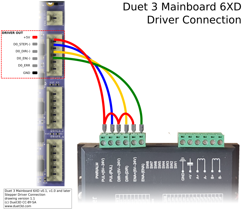
This is the input for the Z stepper driver which is a TB6600 :
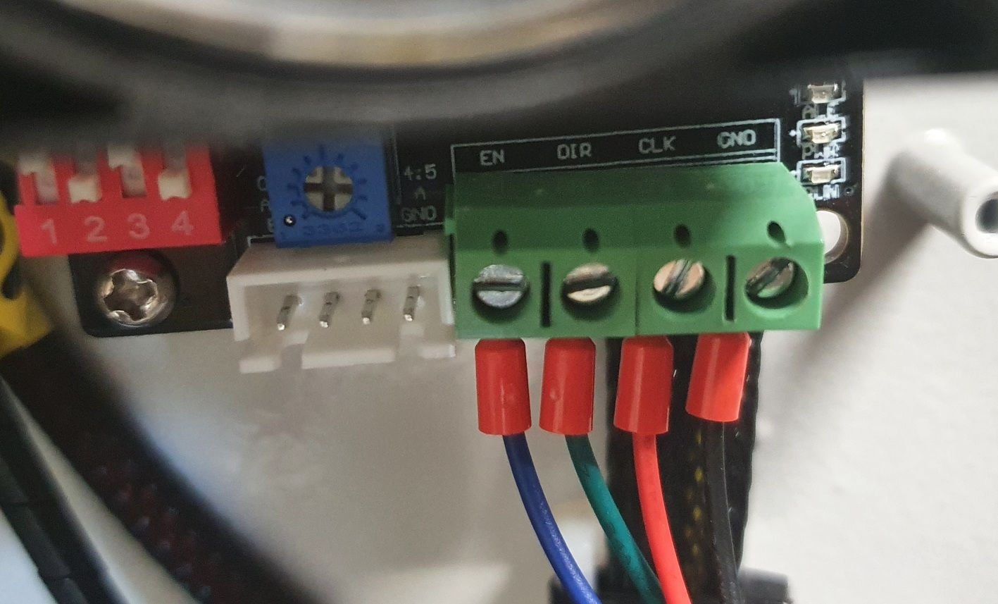
And this is the input for the X and Y stepper driver which are this reference. Note that the connections from factory are made with common grounds (to PUL-, DIR- and EN-) and the signal are passed to the PUL+ DIR+ and EN+.
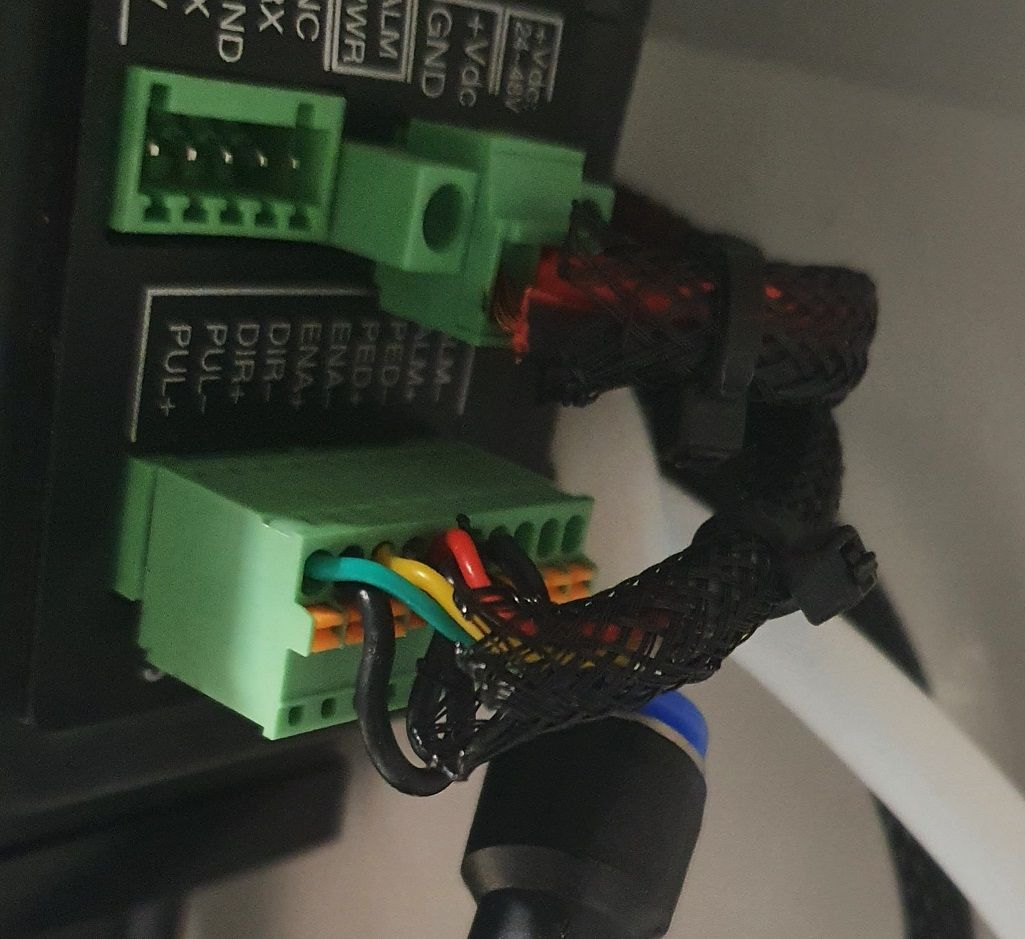
I managed to make it work with my previous machine and the 1XD boards with connections like these :
External stepper for Z TB6600 -> 1XD Board
CLK -> D0_STEP (+)
DIR -> D0_DIR (+)
EN -> D0_EN (-)
GND - > GND (on the IO0)External stepper for X and Y -> 1XD Board
PUL+ -> D0_STEP (+)
DIR+ -> D0_DIR (+)
EN+ -> D0_EN (-)
PUL-, DIR- and EN- > GND (on the IO0)Now I moved to a 6XD board and there are no longer the DIR+ and STEP+ pins on the 6XD board. So I did this :
External stepper for Z TB6600 -> 6XD Board
CLK -> D0_STEP (-)
DIR -> D0_DIR (-)
EN -> D0_EN (-)
GND - > GNDExternal stepper for X and Y -> 6XD Board
PUL+ -> D0_STEP (-)
DIR+ -> D0_DIR (-)
EN+ -> D0_EN (-)
PUL-, DIR- and EN- > GND (on the IO0)It does not work. Nothing moves. I understand the problem that I have is that I only have low signals (-) and no 5V in my wiring, but I don't know how to do it differently...
I checked with a multimeter and the EN signal (from EN- to 5V) and DIR signal (from DIR- to 5V) are working as expected (going from 0 to 5V, when I turn motor on or when I switch direction in the moves). So I don't think it's a firmware issue.
I have a few question :
-
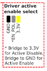
There is a bridge that can be set in the firmware, is it the same as changing the R parameter in the M569 command ?
-
In the 6XD documentation here, there is this sentence :
"To connect a Pololu/StepStick/similar driver to the 6XD a 10K pullup resistor is needed from the Step/Dir/En lines to +5V"
This might be what I need to do, but I don't understand what a "pullup resistor" is and how I should connect them.
I also found this sentence :
"The Step and Dir outputs from the 6XD are either low (when "on") or floating/high-impedance when "off""
From my understanding, it's related to above so the step and dir outputs are at GND when low (on) and are just "whatever" when off ? And the "pullup resistor" would make the "whatever" be 5V when off ? Did I understood that correctly ? -
For the X and Y motors which have all poles (DIR+/DIR-, STEP+/STEP-, EN+/EN-), I see on the same 6XD documentation that it's recommended to have the common 5V to the DIR+ STEP+ and EN+. It's different from the wiring that I have from factory and I'd rather keep them that way if possible as the motor are very hard to access and would recquire a lot of disassembly to modify this wiring... Is it possible to make it work with a 6XD without changing these cables ? Maybe with the same pull up resistor trick ?
Thanks in advance for your help.
-
-
RE: 1XD not workingposted in Duet Hardware and wiring
@chrishamm the mainboard is installed with 3.5.0-rc.1. Same as the Duet Web Control.
I don't see a line with 1XD (not the same as on my other printer, where there is one)Nothing is connected to the 1XD for now. Only power and CAN.
-
1XD not workingposted in Duet Hardware and wiring
Hi,
I'm facing a problem with a new 1XD.
I can't seem to make it work.
I replaced it in my system with a 3HC and it worked flawlessly, no problem with CAN communication.
I replaced it with an old 1XD I took from an other printer and it's working no problem (but I need the old printer so i had to put it back !)I tried to fit a jumper to reset the board, as recommended in the documentation. It did not change anything.
The thing that worries me the most is the fact that the status led is always off.
The 5V red led and the blue VIN led are both turned on.It's a 1XD V1.1
Is this a sign of dead board ? How can I diagnose/solve the problem ?
Thanks in advance.
-
RE: Adapting a printer (expansion board heater control)posted in Duet Hardware and wiring
@dc42 Thank you very much this will work !
-
Adapting a printer (expansion board heater control)posted in Duet Hardware and wiring
Hey
I'm trying to adapt a semi-industrial printer to a duet board.
There are two electronic cards on the printer for now :
- One is a regular marlin printer
- The other is handling all the power (bed, chamber, 220V input, emergency stop, etc).
I would like to replace the first one with a Duet and keep the second one so I don't have to redo all the mains wiring, order some relays etc...
There is only a 5 pin cables between the two cards. And it's the only part i'm unsure about the transition to Duet.
The pins are labeled like this :
B -> Bed -> which goes from 0 to 3.3V when bed is turned on
C -> PTC -> which goes from 0 to 3.3V when chamber is turned on
G -> GND which for me is just the ground (and i used it to measure the other)
V -> 5V which is just 5V
P -> ACCK I have no idea what this one is/does and it's just always at 3.3VHere are my questions :
1 - Any idea what ACCK means ?
2 - The original board seems to be switching the 3.3V and not the ground since there is only one ground for both the bed and the chamber conrol. From my understanding of Duet boards, it's switching the GND and not the 3.3V (Vin).
Any idea how I can wire this secondary board on a duet to make the two heaters (bed and chamber) work ?Thanks in advance for the help.
-
RE: Duet 2 Ethernet disconnect when printing and paneldue connectedposted in PanelDue
@edsped I have added an on/off switch on my PanelDue so I turn it off when I don't use it. Hardware solution to a software problem.