BLTouch mesh bed leveling, but first layer isn't level
-
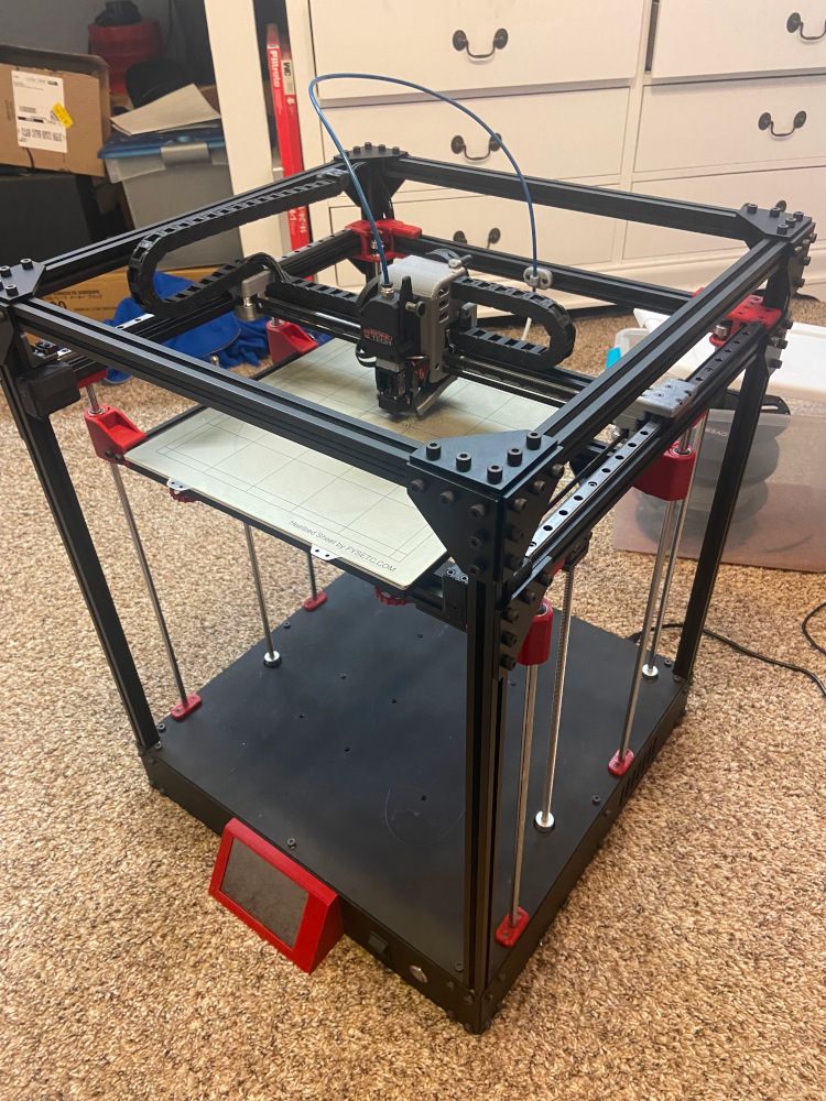
I'm building a custom-designed coreXY printer with dual independent Z axis motors, and am currently running into an absolutely baffling problem with my bed leveling. I've been chasing this problem in circles for weeks, and I'm hoping that a few more knowledgeable sets of eyes might catch something I've missed.
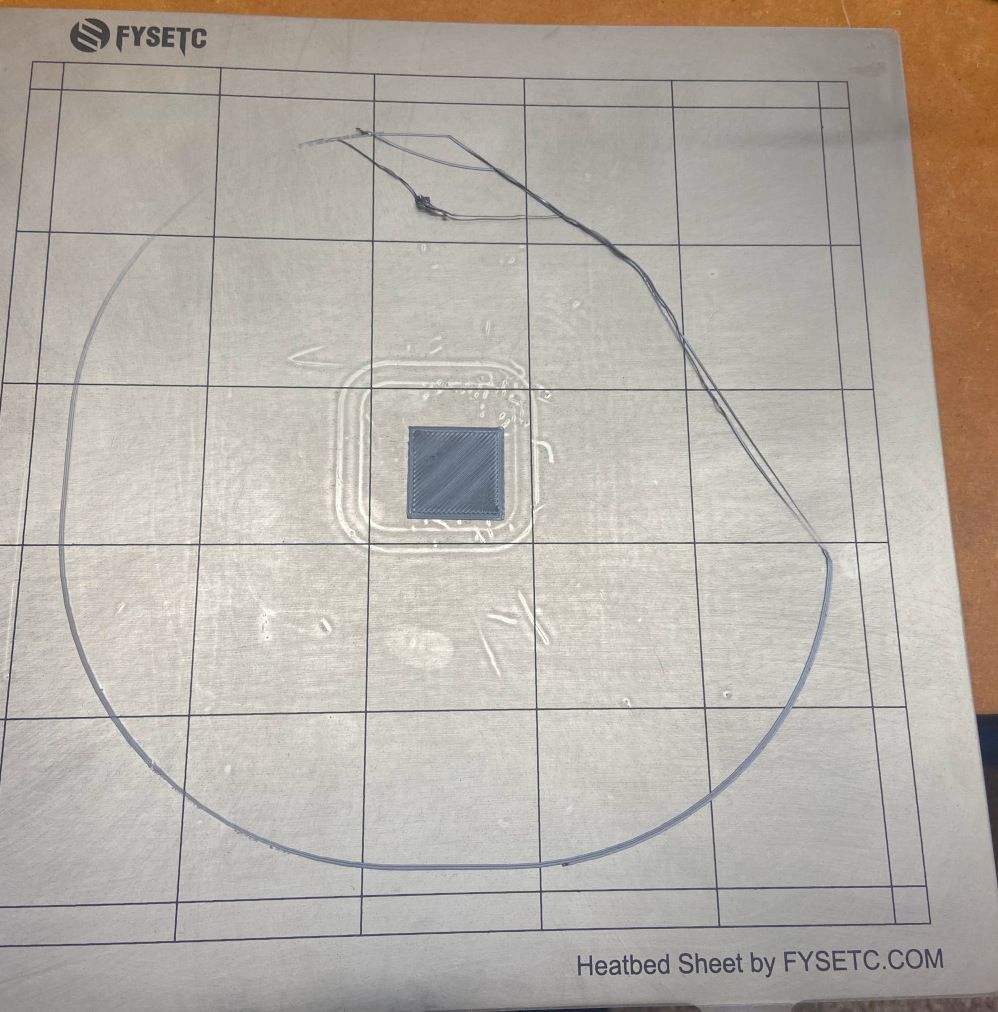
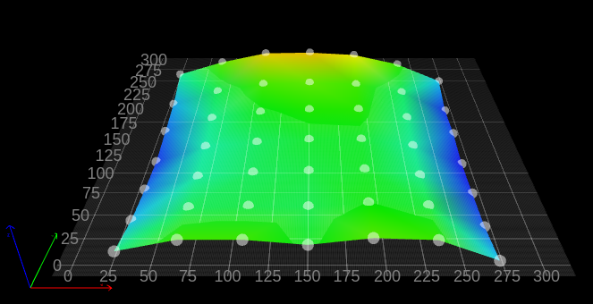
In short, the "level" plane calculated using a BLTouch and mesh bed leveling does not seem to match the bed. The general result is the right side of the bed being significantly further from the nozzle than the left, but also the rear right is the furthest point, and the rear left is the closest.
I know the bed isn't particularly flat, but this issue persists regardless of any bed adjustments. In fact, the printer seems to compensate for these changes, and the high and low spots in the print are exactly the same no matter the absolute flatness or "levelness" of the bed. Also, the high and low spots in the print don't match up with high and low spots in the height map at all. Most of the bed is within about .1-.2mm of flat, with only the outer edges (50mm or so) deviating significantly from that.
Above the 1st level, it prints nearly flawlessly. I have plenty of tweaking left to do, but levelness and distance between higher layers seems to be just fine.
At this point, I'm not even sure where the issue lies. I'm fairly certain the mechanical design is sound. The frame is incredibly rigid, and I've spent hours adjusting the geometry of the various gantries and linear rails and rods to be running as perfectly square and/or level as possible.
Even if something isn't quite right, shouldn't bed leveling be able to adjust for whatever offset or geometry change that introduces? If the toolhead/nozzle were lower at one end of an axis compared to the other, wouldn't the bed just move up or down to cancel that out? Or am i misunderstanding how mesh bed leveling works? It seems to me that this is a software/config issue, but I'm not sure of anything at this point.
Any help would be greatly appreciated.
Images and config files below. Hopefully you're able to get a decent idea of what I'm working with. I can post more config files, images, or renderings from the 3d model if any other information will help.
config.g
M80 C"pson"									; power on

; Basic setup
M575 P1 S1 B57600							; enable PanelDue
G90											; absolute coordinates
M83											; relative extruder moves
M550 P"CoreXY Printer"						; printer name
M669 K1										; CoreXY mode
M552 S1										; enable network
M586 P0 S1									; enable HTTP
M586 P1 S0									; disable FTP
M586 P2 S0									; disable Telnet

; Drives
M569 P0 S1									; drive 0; forwards
M569 P1 S0									; drive 1; backwards
M569 P2 S0									; drive 2; backwards (left Z leadscrew)
M569 P3 S1									; drive 3; forwards (extruder)
M569 P4 S0									; drive 4; backwards (right Z leadscrew)
M584 X0 	Y1 		Z2:4 	E3				; drive mapping
M906 X1800	Y1800	Z1400	E1000	I40		; motor currents (mA); idle factor
M84 S1										; idle timeout
M350 X16 	Y16 	Z16 	E16 	I1		; 16x microstepping with interpolation
M92  X80	Y80		Z400	E415			; steps per mm
M566 X2100	Y2100	Z1200	E600			; jerk (mm/min)
M203 X36000 Y36000	Z3600	E6000			; maximum speed (mm/min)
M201 X15000 Y15000	Z1000	E3000			; acceleration (mm/s^2)
M204 P5000 T10000							; print and travel acceleration

; Axis Limits
M208 X-10 Y-10 Z0 S1						; axis minima
M208 X318 Y300 Z370 S0						; axis maxima

; Endstops
M574 X2 S1 P"xstop"							; X endstop high end; NO; pin xstop
M574 Y1 S1 P"ystop"							; Y endstop low end; NO; pin ystop

; Z-Probe
M950 S0 C"exp.heater3"						; servo 0; pin exp.heater3
M558 P9 C"^zprobe.in" H5 F120 T40000		; Z probe type BLTouch; pin zprobe.in; dive height, speed
G31 P500 X0 Y25 Z2.4						; Z probe trigger value; position offset
M376 H3

; Z-leveling
M671 X370:-58 Y150:150 S10					; leadscrew positions; 10mm correction limit

; Bed heater
M308 S0 P"bedtemp" Y"thermistor" A"Bed Heat" T100000 B4138   		; sensor 0; pin bedtemp; type thermistor; name
M950 H0 C"bedheat" T0                            					; heater 0; pin bedheat; sensor 0
M307 H0 R0.230 K0.266:0.000 D2.74 E1.35 B0			; PID parameters; disable bang-bang
M140 H0
M143 H0 S120                                     					; temperature limit 120C

; Hotend
M308 S1 P"e0temp" Y"thermistor" A"Hotend" T100000 B4138			; sensor 1; pin e0temp; type thermistor; name
M950 H1 C"e0heat" T1											; heater 1; pin e0heat; sensor 1
M307 H1 R3.034 K0.525:0.211 D5.88 E1.35 V23.8 B0					; PID parameters; disable bang-bang
M143 H1 S300													; temperature limit 300C

; Fans
M950 F0 C"fan0" Q20							; fan 0; pin fan0; 20Hz PWM
M106 P0 C"Part Cooling"

M950 F1 C"fan2"								; fan 1; pin fan2
M106 P1 C"Hotend" S1 H1 T50					; fan 1; temperature controlled; heater 1; 50C

; Tools
M563 P0 S"Hotend" D0 H1 F0 L0				; define tool 0
G10 P0 X0 Y0 Z0								; set tool 0 axis offsets
G10 P0 R180 S235							; set initial tool 0 active and standby temperatures to 0C
M572 D0 S0.05								; linear advance
bed.g
M561 ; clear stored mesh G28 ; Bed leveling pass 1 M558 H10 ; 10mm probe dive height ; Define probe points G30 P0 X50 Y150 Z-99999 G30 P1 X150 Y150 Z-99999 G30 P2 X250 Y150 Z-99999 S2 ; and run probe ; Home Z G1 X150 Y150 F40000 ; move to probe point M558 H5 F300 ; dive height, slow home speed G30 ; home Z ; Bed leveling pass 2 G30 P0 X50 Y50 Z-99999 G30 P1 X150 Y50 Z-99999 G30 P2 X250 Y50 Z-99999 G30 P3 X250 Y150 Z-99999 G30 P4 X150 Y150 Z-99999 G30 P5 X50 Y150 Z-99999 G30 P6 X50 Y250 Z-99999 G30 P7 X150 Y250 Z-99999 G30 P8 X250 Y250 Z-99999 S2 ; and run probe ; Home Z G1 X150 Y150 F40000 ; move to probe point M558 H3 F300 ; dive height, slow home speed G30 ; home Z ; Mesh bed leveling M557 X20:280 Y20:280 P7 ; define probe grid G29 ; run probe -
@vockleya
Please post the homeall.g and homez.g files.Is the BLTouch really Y25 away from the nozzle?
So it would then be mounted in the middle of the printhead when I look at the printhead in the photo!?Your bed.g is pretty messed up.
Check out the following post by @jay_s_uk, he posted reference files for a CoreXY with two Z spindles.
However, you should not adopt them 1:1 but adapt them for your printer.https://forum.duet3d.com/topic/29730/mistake-true-bed-levelling-g32/4
Google Translate
-- Original Text --Poste bitte mal die homeall.g und homez.g Datei.
Ist der BLTouch wirklich Y25 von der Düse entfernt ?
Er wäre dann also in der Mitte des Druckkopfes montiert, wenn ich mir den Druckkopf auf dem Foto ansehe !?Deine bed.g ist ziemlich durcheinander.
Gucke Dir mal folgenden Post von @jay_s_uk an, er hat dort Referenzdateien für ein CoreXY mit zwei Z-Spindeln gepostet.
Du solltest sie aber nicht 1:1 übernehmen sondern für Deinen Drucker anpassen.
Link siehe oben ! -
@vockleya - Nice Design! It looks very solid.
From your description, I believe you correctly understand the function of mesh bed leveling. It should adjust for the variations shown in your height map.
The general shape and deflection of your height map looks reasonable. What looks like a bow up in the center of the bed in the X direction could be either a bow up in the bed, or a bow down in the middle of the gantry. Remember, the z probe measures the distance from the probe to the bed and there is no guarantee the probe is always on the same plane.
Neither of my two CoreXY printers is a twin-Z, so I can't comment about the leveling part of bed.g. The rest seems OK.
Your comment about the height map not matching you observed first layer seems correct.
My advice - I had a similar issue with one of my CoreXY printers. In the end, my solution had three components - First was making sure the surface of the build plate was very clean. I tried both alcohol and ammonia and found ammonia worked better for me when printing PLA and alcohol was better with PETG. Second, giving the bed plenty of time to heat evenly was important. My printer has a 6mm aluminum bed and it takes about 15 minutes for the top corned to get fully up to temp. I'm in the process of adding insulation on the bottom. Third was finding a z-offset that was a good compromise across the bed. In theory, mesh compensation should make this redundant, but I made test squares like you have in each corner and used baby-stepping while each was printing to find the ideal offset. Then I adjusted my tool z offset to hit the middle of the baby steps range.
Other things you can look for:
-
Your printhead rocking on the X rail, or the whole gantry rocking on the Y rail. If there is play, it's possible your cable chains or bowden tube could be rocking the printhead so that the probe offset is changing at different X and Y positions.
-
If the two Y rails are not super-parallel and/or you belt tensions are not close to equal, and there is play in the blocks, the belts could be torquing the gantry during movement. This might not be seen when the print head stops to probe the bed.
-
-
If you have two Z drives then shouldn't you have only two probe points in your bed.g ?
I.e one near each lead screw so you can level the bed. -
Thanks for all the ideas. I've got a lot more testing to do now.
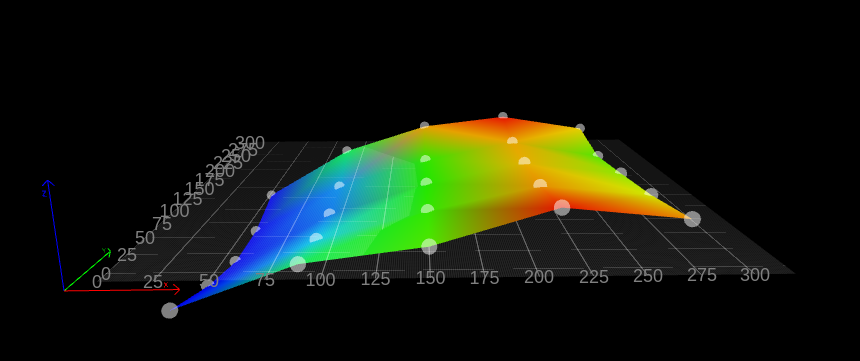
When I manually level the bed to the nozzle and then run G29, I get the mesh below, I think the entire toolhead is deflecting as it travels across the X axis. I'll need to do a bit of a redesign to stiffen it more. I also want to add 2 fixed probe points attached directly to the Z gantry, insteaf of using the bed for auto leveling. That should give a more reliable starting point.
The homing and bed probing files seem to be working correctly, so I don't think thats the issue. Although I've cleaned them up a bit and all 3 are included below.
bed.g
M561				; clear stored mesh
G28				; home all

; rough bed leveling pass
M558 H10 F1500			; dive height, speed
G30 P0 X50  Y150  Z-99999	; probe points
G30 P1 X150 Y150  Z-99999
G30 P2 X250 Y150  Z-99999 S2	; and run probe

; fine bed leveling pass
M558 H3 F300			; dive height, speed
G30 P0 X100 Y100 Z-99999	; probe points
G30 P1 X200 Y100 Z-99999
G30 P2 X100 Y200 Z-99999
G30 P3 X200 Y200 Z-99999 S2	; and run probe

; mesh bed leveling
M557 X20:280 Y20:280 P3		; probe grid
G29				; run probe
homeall.g
; Home X/Y
G91				; relative positioning
G1 H2 Z5 F1000			; drop bed
G1 H1 X320 Y-320 F10000		; move to X or Y endstop (fast)
G1 H1 X320	F10000		; move to X endstop (fast)
G1 H1 Y-320	F10000		; move to Y endstop (fast)
G1 X-5 Y5 F10000		; go back a few mm
G1 H1 X320 F1000		; move to X endstop (slow)
G1 H1 Y-320	F1000		; move to Y endstop (slow)
G90				; absolute positioning

; Home z
M98 P"homez.g"
homez.g
G91				; relative positioning
G1 H2 Z5 F6000			; drop bed
G90				; absolute positioning
G1 X150 Y150 F30000		; move to probe point
M558 H10 F2500			; fast home
G30				; home Z
M558 H3 F300			; slow home
G30				; home Z