Printer does not recognize bed size
-
Printer does not recognize bed size and only prints half the file:
; set motor currents (mA) and motor idle factor in per cent
M84 S30 ; Set idle timeout; Axis Limits
M208 X90 Y170 Z0 S1 ; set axis minima
M2; Configuration file for Duet WiFi (firmware version 3.3)
; executed by the firmware on start-up
;
; generated by RepRapFirmware Configuration Tool v3.3.12 on Wed Aug 24 2022 12:56:11 GMT+0200 (Mitteleuropäische Sommerzeit); General preferences
M575 P1 S1 B57600 ; enable support for PanelDue
G90 ; send absolute coordinates...
M83 ; ...but relative extruder moves
M550 P"DUKA1300" ; set printer name; Network
M552 S1 ; enable network
M586 P0 S1 ; enable HTTP
M586 P1 S0 ; disable FTP
M586 P2 S0 ; disable Telnet; Drives
M569 P1 S1 ; physical drive 0 goes forwards
M569 P1 S1 ; physical drive 1 goes forwards
M569 P2 S0 ; physical drive 2 goes forwards
M569 P3 S0 ; physical drive 3 goes forwards extruder1
M569 P4 S1 ; physical drive 4 goes forwards
M584 X0 Y1 Z2 E3:4 ; set drive mapping
M350 X16 Y16 Z16 E16:16 I1 ; configure microstepping with interpolation
;M92 X80.00 Y80.00 Z400.00 E420.00:420.00 ; set steps per mm
M92 X80.00 Y80.00 Z640.00 E320.20:320.51 ; set steps per mm
M566 X900.00 Y900.00 Z120.00 E120.00:120.00 ; set maximum instantaneous speed changes (mm/min)
M203 X6000.00 Y6000.00 Z1200.00 E1200.00:1200.00 ; set maximum speeds (mm/min)
M201 X500.00 Y500.00 Z40.00 E250.00:250.00 ; set accelerations (mm/s^2)
M906 X1800 Y1800 Z2000 E1800:1800 I30 08 X660 Y910 Z1200 S0 ; set axis maxima; Endstops
M574 X1 S1 P"xstop" ; configure switch-type (e.g. microswitch) endstop for low end on X via pin xstop
M574 Y1 S1 P"ystop" ; configure switch-type (e.g. microswitch) endstop for low end on Y via pin ystop
;M574 Z2 S1 P"zstop" ; configure switch-type (e.g. microswitch) endstop for high end on Z via pin zstop
;M574 Z2 S2 ; configure Z-probe endstop for high end on Z
; Z-Probe
M558 P1 C"!zprobe.in" H5 F120 T6000 ; set Z probe type to unmodulated and the dive height + speeds
G31 P1000 X-20 Y80 Z0.492 ; set Z probe trigger value, offset and trigger height
M557 X125:710Y50:810S100 ; define mesh grid; Heaters
M308 S0 P"e1temp" Y"thermistor" T100000 B4138 ; configure sensor 0 as thermistor on pin e1temp
M950 H0 C"e1heat" T0 ; create nozzle heater output on e1heat and map it to sensor 0
M307 H0 R1.797 K0.742:0.000 D7.57 E1.35 S1.00 B0 V23.8 ; disable bang-bang mode for heater and set PWM limit
M143 H0 S250 ; set temperature limit for heater 0 to 250C
M308 S1 P"e0temp" Y"thermistor" T100000 B4138 ; configure sensor 1 as thermistor on pin e0temp
M950 H1 C"e0heat" T1 ; create nozzle heater output on e0heat and map it to sensor 1
M307 H1 R1.797 K0.742:0.000 D7.57 E1.35 S1.00 B0 V23.8 ; disable bang-bang mode for heater and set PWM limit
M143 H1 S250 ; set temperature limit for heater 1 to 250C
M308 S2 P"bedtemp" Y"thermistor" T100000 B4138 ; configure sensor 2 as thermistor on pin bedtemp
M950 H2 C"bedheat" T2 ; create bed heater output on bedheat and map it to sensor 2
M307 H2 R0.283 K0.463:0.000 D7.17 E1.35 S1.00 B0 ; enable bang-bang mode for the bed heater and set PWM limit
M140 H2 ; map heated bed to heater 2
M143 H2 S280 ; set temperature limit for heater 2 to 280C; Fans
;M950 F0 C"fan0" Q500 ; create fan 0 on pin fan0 and set its frequency
;M106 P0 S1 H0 T45 ; set fan 0 value. Thermostatic control is turned on
M950 F1 C"fan1" Q500 ; create fan 1 on pin fan1 and set its frequency
;M106 P1 S1 H1 T45 ; set fan 1 value. Thermostatic control is turned on; Tools
;M563 P0 D0 H0 F0 ; define tool 0
;G10 P0 X0 Y0 Z0 ; set tool 0 axis offsets
;G10 P0 R0 S0 ; set initial tool 0 active and standby temperatures to 0C
M563 P1 D1 H1 F1 ; define tool 1
G10 P1 X45 Y45 Z0 ; set tool 1 axis offsets
G10 P1 R0 S0 ; set initial tool 1 active and standby temperatures to 0C; Custom settings are not defined
; Miscellaneous
M911 S10 R11 P"M913 X0 Y0 G91 M83 G1 Z3 E-5 F1000" ; set voltage thresholds and actions to run on power lossSlicer Cura:
-
@axiom said in Printer does not recognize bed size:
; Axis Limits
M208 X90 Y170 Z0 S1 ; set axis minima
M2; Configuration file for Duet WiFi (firmware version 3.3)
; executed by the firmware on start-up
;
; generated by RepRapFirmware Configuration Tool v3.3.12 on Wed Aug 24 2022 12:56:11 GMT+0200 (Mitteleuropäische Sommerzeit)That's not right. You have a M208 command that sets the axis minimum positions; then an M2 command which doesn't make sense, then what should be the start of the file. I don't see a M208 command to set the maximum XYZ values.
Duet WiFi hardware designer and firmware engineer
Please do not ask me for Duet support via PM or email, use the forum
http://www.escher3d.com, https://miscsolutions.wordpress.com -
@dc42
Oh, there was an error copying the gcode:
Here are the lines:
; Axis Limits
M208 X90 Y170 Z0 S1 ; set axis minima
M208 X660 Y910 Z1200 S0 ; set axis maxima; Endstops
M574 X1 S1 P"xstop" ; configure switch-type (e.g. microswitch) endstop for low end on X via pin xstop
M574 Y1 S1 P"ystop" ; configure switch-type (e.g. microswitch) endstop for low end on Y via pin ystop
;M574 Z2 S1 P"zstop" ; configure switch-type (e.g. microswitch) endstop for high end on Z via pin zstop
;M574 Z2 S2 ; configure Z-probe endstop for high end on Z
; Z-Probe
M558 P1 C"!zprobe.in" H5 F120 T6000 ; set Z probe type to unmodulated and the dive height + speeds
G31 P1000 X-20 Y80 Z0.492 ; set Z probe trigger value, offset and trigger height
M557 X125:710Y50:810S100 ; define mesh grid -
@dc42
Here is the full code again:generated by RepRapFirmware Configuration Tool v3.3.12 on Wed Aug 24 2022 12:56:11 GMT+0200 (Mitteleuropäische Sommerzeit)
; General preferences
M575 P1 S1 B57600 ; enable support for PanelDue
G90 ; send absolute coordinates...
M83 ; ...but relative extruder moves
M550 P"DUKA1300" ; set printer name; Network
M552 S1 ; enable network
M586 P0 S1 ; enable HTTP
M586 P1 S0 ; disable FTP
M586 P2 S0 ; disable Telnet; Drives
M569 P1 S1 ; physical drive 0 goes forwards
M569 P1 S1 ; physical drive 1 goes forwards
M569 P2 S0 ; physical drive 2 goes forwards
M569 P3 S0 ; physical drive 3 goes forwards extruder1
M569 P4 S1 ; physical drive 4 goes forwards
M584 X0 Y1 Z2 E3:4 ; set drive mapping
M350 X16 Y16 Z16 E16:16 I1 ; configure microstepping with interpolation
;M92 X80.00 Y80.00 Z400.00 E420.00:420.00 ; set steps per mm
M92 X80.00 Y80.00 Z640.00 E320.20:320.51 ; set steps per mm
M566 X900.00 Y900.00 Z120.00 E120.00:120.00 ; set maximum instantaneous speed changes (mm/min)
M203 X6000.00 Y6000.00 Z1200.00 E1200.00:1200.00 ; set maximum speeds (mm/min)
M201 X500.00 Y500.00 Z40.00 E250.00:250.00 ; set accelerations (mm/s^2)
M906 X1800 Y1800 Z2000 E1800:1800 I30 ; set motor currents (mA) and motor idle factor in per cent
M84 S30 ; Set idle timeout; Axis Limits
M208 X90 Y170 Z0 S1 ; set axis minima
M208 X660 Y910 Z1200 S0 ; set axis maxima; Endstops
M574 X1 S1 P"xstop" ; configure switch-type (e.g. microswitch) endstop for low end on X via pin xstop
M574 Y1 S1 P"ystop" ; configure switch-type (e.g. microswitch) endstop for low end on Y via pin ystop
;M574 Z2 S1 P"zstop" ; configure switch-type (e.g. microswitch) endstop for high end on Z via pin zstop
;M574 Z2 S2 ; configure Z-probe endstop for high end on Z
; Z-Probe
M558 P1 C"!zprobe.in" H5 F120 T6000 ; set Z probe type to unmodulated and the dive height + speeds
G31 P1000 X-20 Y80 Z0.492 ; set Z probe trigger value, offset and trigger height
M557 X125:710Y50:810S100 ; define mesh grid; Heaters
M308 S0 P"e1temp" Y"thermistor" T100000 B4138 ; configure sensor 0 as thermistor on pin e1temp
M950 H0 C"e1heat" T0 ; create nozzle heater output on e1heat and map it to sensor 0
M307 H0 R1.797 K0.742:0.000 D7.57 E1.35 S1.00 B0 V23.8 ; disable bang-bang mode for heater and set PWM limit
M143 H0 S250 ; set temperature limit for heater 0 to 250C
M308 S1 P"e0temp" Y"thermistor" T100000 B4138 ; configure sensor 1 as thermistor on pin e0temp
M950 H1 C"e0heat" T1 ; create nozzle heater output on e0heat and map it to sensor 1
M307 H1 R1.797 K0.742:0.000 D7.57 E1.35 S1.00 B0 V23.8 ; disable bang-bang mode for heater and set PWM limit
M143 H1 S250 ; set temperature limit for heater 1 to 250C
M308 S2 P"bedtemp" Y"thermistor" T100000 B4138 ; configure sensor 2 as thermistor on pin bedtemp
M950 H2 C"bedheat" T2 ; create bed heater output on bedheat and map it to sensor 2
M307 H2 R0.283 K0.463:0.000 D7.17 E1.35 S1.00 B0 ; enable bang-bang mode for the bed heater and set PWM limit
M140 H2 ; map heated bed to heater 2
M143 H2 S280 ; set temperature limit for heater 2 to 280C; Fans
;M950 F0 C"fan0" Q500 ; create fan 0 on pin fan0 and set its frequency
;M106 P0 S1 H0 T45 ; set fan 0 value. Thermostatic control is turned on
M950 F1 C"fan1" Q500 ; create fan 1 on pin fan1 and set its frequency
;M106 P1 S1 H1 T45 ; set fan 1 value. Thermostatic control is turned on; Tools
;M563 P0 D0 H0 F0 ; define tool 0
;G10 P0 X0 Y0 Z0 ; set tool 0 axis offsets
;G10 P0 R0 S0 ; set initial tool 0 active and standby temperatures to 0C
M563 P1 D1 H1 F1 ; define tool 1
G10 P1 X45 Y45 Z0 ; set tool 1 axis offsets
G10 P1 R0 S0 ; set initial tool 1 active and standby temperatures to 0C; Custom settings are not defined
; Miscellaneous
M911 S10 R11 P"M913 X0 Y0 G91 M83 G1 Z3 E-5 F1000" ; set voltage thresholds and actions to run on power loss -
Can you post your homing files? Perhaps you have something strange going on in there.
-
@Phaedrux
Here are all 4 files:
home all
Home x
home y
and home z
I'm curious if you can discover something bad!
Many greetings,
Don; homeall.g
; called to home all axes
;
; generated by RepRapFirmware Configuration Tool v3.3.12 on Wed Aug 24 2022 12:56:11 GMT+0200 (Mitteleuropäische Sommerzeit)
G91 ; relative positioning
G1 H2 Z5 F6000 ; lift Z relative to current position
G1 H1 X-580 Y-760 F1800 ; move quickly to X and Y axis endstops and stop there (first pass)
G1 H2 X10 Y10 F1800 ; go back a few mm
G1 H1 X-580 Y-760 F800 ; move slowly to X and Y axis endstops once more (second pass)
;G1 H1 Z705 F360 ; move Z up stopping at the endstop
G90
G1 X10 Y10 F2400
G30
G90 ; absolute positioning
;G92 Z700 ; set Z position to axis maximum (you may want to adjust this); Uncomment the following lines to lift Z after probing
G91 ; relative positioning
G1 Z5 F100 ; lift Z relative to current position
G90 ; absolute positioning; homex.g
; called to home the X axis
;
; generated by RepRapFirmware Configuration Tool v3.3.12 on Wed Aug 24 2022 12:56:11 GMT+0200 (Mitteleuropäische Sommerzeit)
G91 ; relative positioning
G1 H2 Z5 F6000 ; lift Z relative to current position
G1 H1 X-505 F1800 ; move quickly to X axis endstop and stop there (first pass)
G1 H2 X5 F6000 ; go back a few mm
G1 H1 X-505 F360 ; move slowly to X axis endstop once more (second pass)
G1 H2 Z-5 F6000 ; lower Z again
G90 ; absolute positioning; homey.g
; called to home the Y axis
;
; generated by RepRapFirmware Configuration Tool v3.3.12 on Wed Aug 24 2022 12:56:11 GMT+0200 (Mitteleuropäische Sommerzeit)
G91 ; relative positioning
G1 H2 Z5 F6000 ; lift Z relative to current position
G1 H1 Y-50 F1800 ; move quickly to Y axis endstop and stop there (first pass)
G1 H2 Y5 F6000 ; go back a few mm
G1 H1 Y-505 F360 ; move slowly to Y axis endstop once more (second pass)
G1 H2 Z-5 F6000 ; lower Z again
G90 ; absolute positioning; homez.g
; called to home the Z axis
;
; generated by RepRapFirmware Configuration Tool v3.3.12 on Wed Aug 24 2022 12:56:11 GMT+0200 (Mitteleuropäische Sommerzeit)
G91 ; relative positioning
G1 H2 Z5 F6000 ; lift Z relative to current position
G90 ; absolute positioning
G1 X5 Y85 F6000 ; go to first probe point
G30 ; home Z by probing the bed; Uncomment the following lines to lift Z after probing
;G91 ; relative positioning
;G1 Z5 F100 ; lift Z relative to current position
;G90 ; absolute positioning -
Nothing out of the ordinary there. What does your build platter image look like in Cura? I believe it blanks out areas it thinks it cannot reach.
Are you sure belts or pulleys are not slipping or motors skipping steps?
-
@Phaedrux
In the code I entered the position of the nozzle (distance nozzle to end stop) as the starting position: 50 and 115mm:
M208 X50 Y115 Z0 S1 ; set axis minima and the same in the slicer settings:
Is there a misconception here?
-
@axiom said in Printer does not recognize bed size:
Is there a misconception here?
Yes I think so, For those fields you could probably leave them as 0 and see if that improves your situation.
-
@Phaedrux said in Printer does not recognize bed size:
@axiom said in Printer does not recognize bed size:
Is there a misconception here?
Yes I think so, For those fields you could probably leave them as 0 and see if that improves your situation.
I think so too. From a firmware perspective, the axes minima are relative to the position of the end stops. But the slicer has no concept of end stop switches, let alone their positions relative to the build surface. So I think the slicer axes min should be zero and the max should be whatever the travel length is. Otherwise one would be doing a double compensation.
-
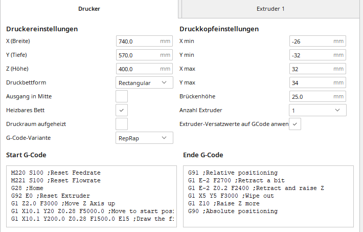
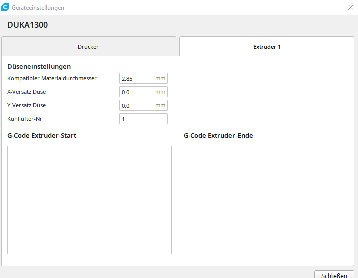
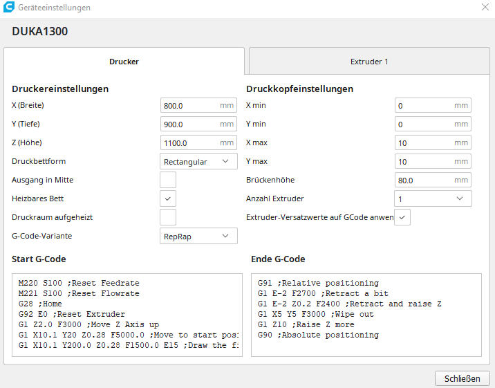
My German is a little rusty, so I had to open Cura to see the English. The Druckkopfeinstellungen or Printhead Settings tell Cura the general size of your print head, so that if you are printing multiple objects consecutively, it will lay them out to avoid the print head hitting the existing objects on the bed.
At 115 and 50 mm you've told it your print head is extremely large.
 Screen Shot 2022-11-13 at 10.39.50 AM.png
https://all3dp.com/2/cura-printhead-settings-simply-explained/
-
@Phaedrux
Hello, I was on a business trip for 1 week and was only able to try your tips now.
In fact, after I set xmin and ymin to 0 in Cura, the printer printed the entire circle...you guessed right! However, the start position in the control panel changes. I suspect something is still wrong in the Cura startup code. Can you give me a starting code for Cura that is as simple as possible? Here again the start and end code from Cura, which I took over apart from the speeds...
M220 S100 ;Reset Feedrate
M221 S100 ;Reset Flowrate
G28 ;Home
G92 E0 ;Reset Extruder
G1 Z2.0 F3000 ;Move Z Axis up
G1 X10.1 Y20 Z0.28 F5000.0 ;Move to start position
G1 X10.1 Y200.0 Z0.28 F1500.0 E15 ;Draw the first line
G1 X10.4 Y200.0 Z0.28 F5000.0 ;Move to side a little
G1 X10.4 Y20 Z0.28 F1500.0 E30 ;Draw the second line
G92 E0 ;Reset Extruder
G1 Z2.0 F3000 ;Move Z Axis up -
@axiom Moin axiom,
As „Start G-Code“, this here should be sufficient:
G28 ; Home
M83 ; set extruder to relative mode
G92 E0 ; reset extruder’s relative position to 0
Most other instructions to prepare the printer for a job should better be written into the start.g macro on SD card.
I don’t quite understand this here:
However, the start position in the control panel changes.
With „control panel“, do you mean DWC, PanelDue or something else?
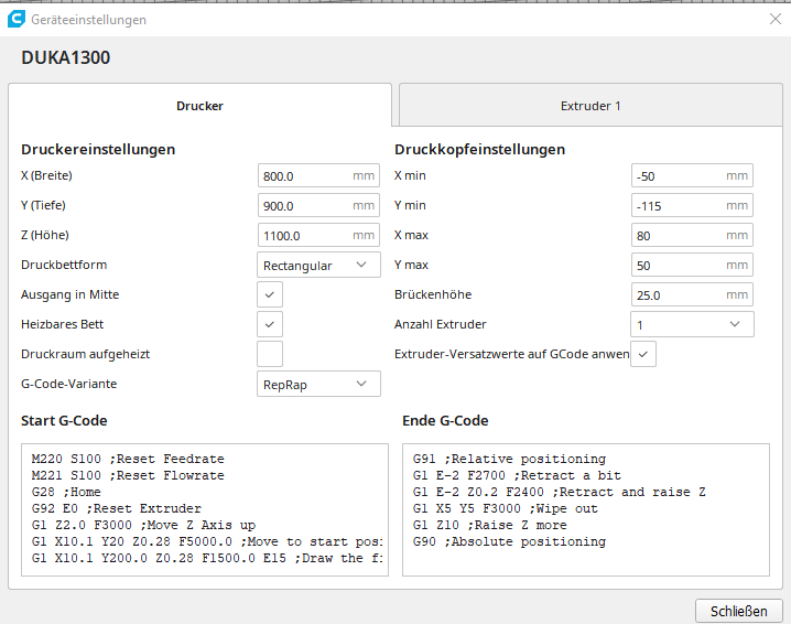
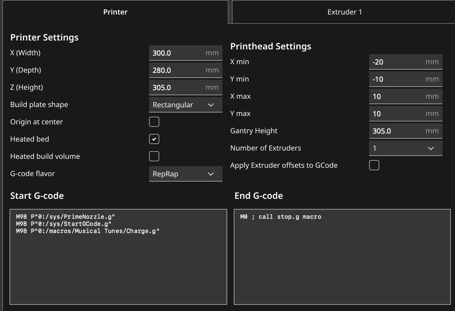
Generally, it’s quite simple. In your Druckeinstellungen, you told Cura about the size of your printer and the origin of the coordinate system: „Ausgang in Mitte“ (BTW: strange translation of ‚center origin‘) is deselected, so the origin should be front left. At least, that’s what Cura assumes.
Now, depending on where you place your print object in Cura, this should correspond to its placement on your print bed … as far as you defined the printer’s X/Y origin to be at the front left. If the position doesn’t match, there’s something wrong with either the size values in the Druckereinstellungen of Cura or with the axes-settings of your printer.