Intergrating a precision piezo in Duet-wifi
-
I purchased a Precision Piezo kit (original from precision piezo) and I am truly disappointed with both their support and response. The Chat nobody replies and neither to my e-mails. The online documentation is inadequate. Now I come to my issue. I am still playing around with wireing it but the kit I bought has a V2.85 board.
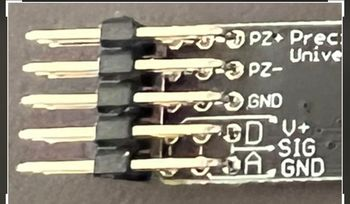
My issue is that the board has 15 pins coming out and there is no clear explanation why there are so many pins.
Starting from the top row- the two top pins are marked PZ+ and PZ- which I assume connect to the piezo disk ( again do not know why I have 3 disks)
the next row of pins is marked ground and have a white marking indicating the 3 pins are all connected
the next two rows are marked confusingly. Knowing how delicate electronic components are, I am reluctant to try to wire it blindly...
from what I gathered, the connections to the duet are SIGNAL /GROUND/POS+VeThe pins on the duet board are identified by starting from the side of the expansion slot.
FIRST PIN is the positive which is the 3.3V pin n slot
SECOND PIN -unused
THIRD PIN- Ground
FOURTH PIN - Z Probe incould someone confirm these connections and tell me why there are so many pins? do not want to fry anything.
Many thanks!
-
The reason that there many pins is that you can easily connect multiple piezo disks.
For example, I have 4 disks in my setup (2 x 2 in parallel, 1 for pickup, 1 for noise canceling)
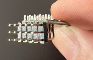
The confusing part is that the piezo's connect horizontally but the connection towards the Duet is a vertical connectionThis is the order - I am using the first image as a reference here, second image inverts the pcb.
As you see on the silkscreen the 2 bottom vertical stacks are the same:
Top pin connects to Duet Z Probe in
Middle pin connects to Duet Ground
Bottom pin connects to Duet 3.3VThe pins to the top are 3 horizontal pairs to connect piezo disks to, make sure you respect the polarity (use a multimeter if you are not sure) otherwise the board will perform bad
The pins in the middle are just ground and are generally not used.
here is an attempt explaining it with Paint:
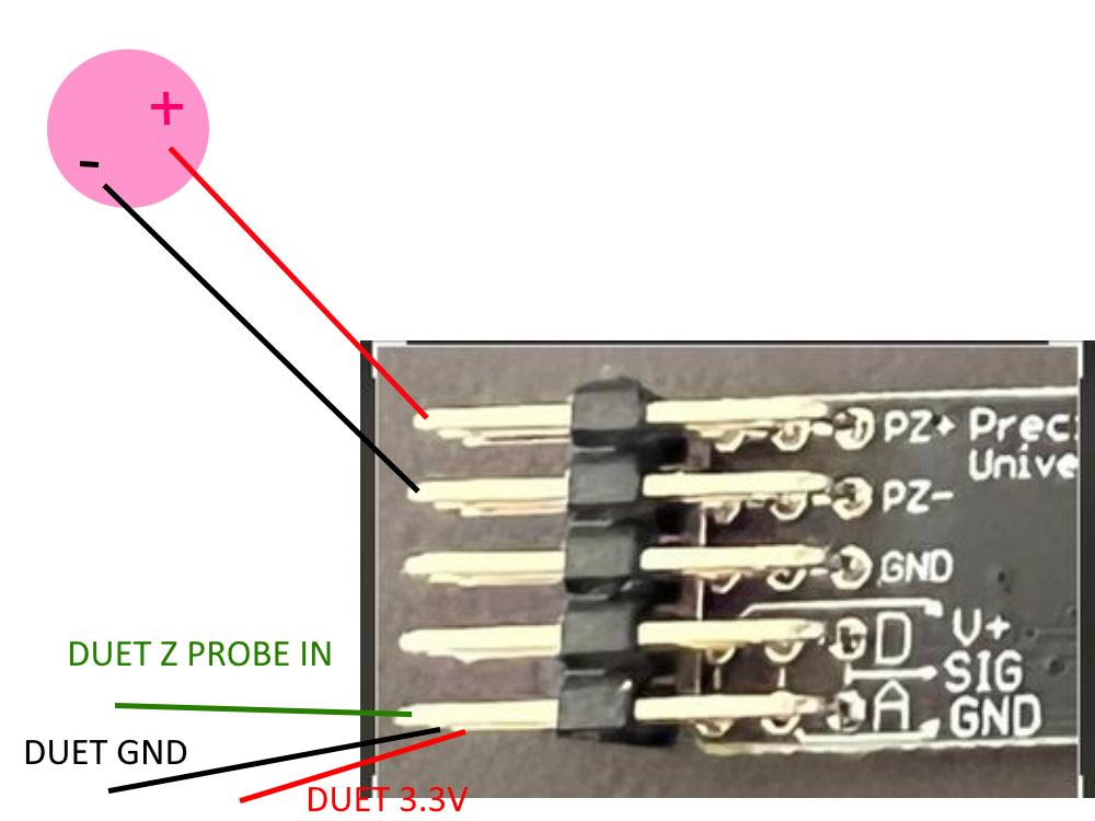
Hope this helps
-
@whosrdaddy
Thanks so much as you have given me all in one go.
I still have to wad through the firmware bit to have this operational,
Thanks again. -
@mendelevium What board do you have? I can give you my setup if you want (Duet 2 Wifi here)
-
@whosrdaddy
I have the duet 2 wifi board
Thanks -
These are my relevant lines in config.g, I use the piezo's as underbed Z-probe:
M574 Z1 S2 ; Set endstops controlled by probe M558 P8 X0 Y0 Z1 H6 I1 R0.3 F900 T9000 A6 S0.015 ; Piezo V2 probe used for homing Z axis, dive height 2cm, probe speed 600mm/min, travel speed 150mm/s G31 P500 X0 Y0 Z-0.14 ; Set Z probe trigger value, offset and trigger height -
@whosrdaddy
Thanks, that is a starter. I wish to check if all is working really to see if the piezo and its wireing is ok. before moving on.
I did not have an intention of running it under the bed but I am still open to anything. My printer runs on ballscrews on all axis. I have a 220V aluminium plate heated via a silicone pad heater. The heatbed is a 6mm precision aluminium plate and a 3mm glass plate on top -
@whosrdaddy
For homing Z, I used a high precision CNC machine reference switch. -
@whosrdaddy
I am having a problem because the PCB seems not to be powered.
for the power to be supplied to the pins on the board, is there a need of some specific command to get the pins powered? or the supply should be already there?
If this is so, I need to open up the controller and check the wireing.... -
The piezo board should receive power from the Duet.
you are using the Z probe in connector on the Duet right?