Revisited: Connector question...
-
Re: PWM Issues
I've read this and some other threads on here, but I must confess to being somewhat confused (which isn't too hard!)
I too have a spindle (a Sorotec SFM1000 PV-ER, which is a clone of the Mafell FM1000 PV-ER with exactly the same specification and built by the same manufacturer) and the PWM converter from Amazon.
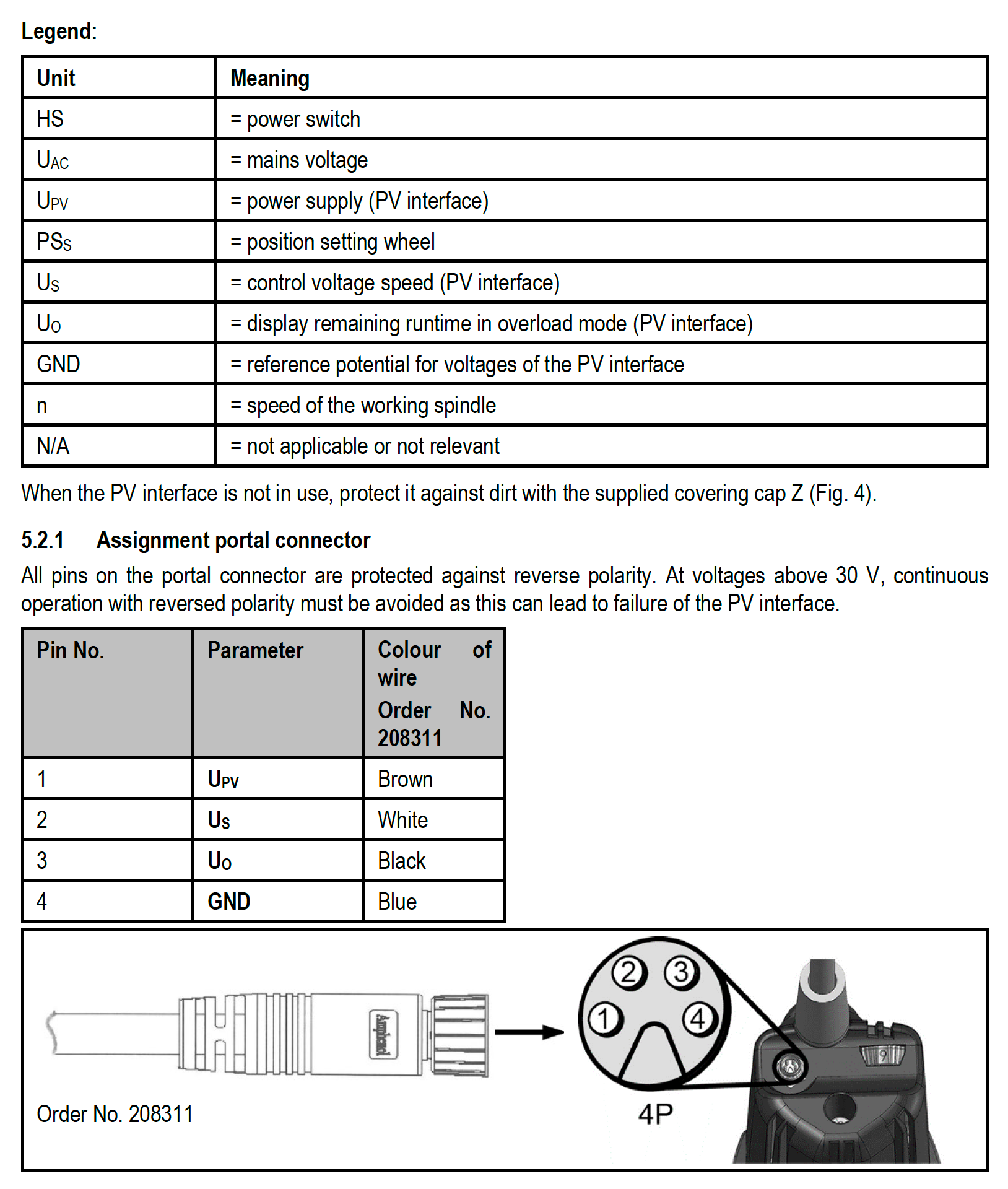
What I'm confused about is that these machines have a 4-pin connector, as shown below:

...but the guidance documents seem to only refer to only 3 (i.e. relating to the brown, white and black wire colours), as shown below:
I appreciate the answer to this could be quite simple (assuming the colours of the Sorotec correspond to those of the Mafell and/or AMB/Kress milling motors - I'll check).
Where did those of you with the Mafell or Sorotec milling motors connect the 4th wire?
Thank you.
EDIT: This extract from a table in the Sorotec manual might be a giveaway:
Upv = power supply (PV interface)
Us = control voltage speed (PV interface)
Uo = display remaining runtime in overload mode (PV interface)
GND = reference potential for voltages of the PV interface...so I'm thinking the Upv, Us and GND are the relevant connectors, but what do I need to do with the Uo?
-
@Nightowl said in Revisited: Connector question...:
Uo = display remaining runtime in overload mode (PV interface)
I've found another clone at https://www.stepcraft-systems.com/images/SC-Service/Anleitungen-EN/Operating-Manual-MM-800-1000-DI.pdf which has some interesting information in chapters 5.4.1 and 5.4.2. According to this, the runtime is a value to watch for in case of overloads.
My interpretation is, when the motor overheats due to overload, table 5.4.2 says, in case of overload <5s, after 5 seconds it will turn off. To detect, the U0 will be 5 volts (starting at 0 volt if all is ok). To analyse, you would need a ADC (analog ditigal converter) for voltage. Duet hardware is 3.3 volt based, so if using some input pin for it, you'll need a voltage divider or similar to avoid damage and there is maximum current to be (considered/)complied.
-
I think I understand things as far as that's concerned, @JoergS5, thank you, but I'm trying to confirm the corresponding pinouts. For example, if is this correct (and I'm not saying it is!
:")
Upv (Brown) = +24V (Brown)
Us (White) = 0-10V (Green)
GND (Black) = GND (White)...what/how am I supposed to connect Uo (Black) to?

Few things are more dangerous than taking the advice of someone who thinks he knows what he's doing.
I'm still on my learning curve, so take everything I say with caution!RatRig 1075, Duet3 MB6HC, Sorotec SFM 1000 PV-ER milling motor, Hobbyist
-
@Nightowl if it outputs 5V on fault you could connect it to an input and setup a trigger to take an appropriate action if that happens. Does the manufacturer not provide any more details?
-
@Nightowl I've checked the Sorotec homepage. They mention:
Overload detector with LED status display, can also be evaluated externally via plug pin. ...
Unique feature: overload display by changing the speed setting wheel lighting to red.So this is visually and optional controllable by software. But an option is to ask Sorotec for a recommended solution. I did not find any circuit diagram.
koswix in https://forum.duet3d.com/topic/14243/wiring-a-pv-cable-from-a-mafell-router-into-the-duet/10 had the same question as you without an answer. I think it would be sufficient to connect it to a trigger pin, the voltage high is not important (you probably want to pause in all cases of overload), so pin status from off to on would be sufficient imho.
But be aware of lowering it to 3.3 V. From documentation: "IO output pins can be used as inputs, but are only 3.3V tolerant. "
If you have the 6HC board, the IO3,4,5,6,7 have analog in pins, so they are able to read analog values in the sense of ADC values I described above. I don't know by heart however how to configure them. (probably M950, M581, M582)
-
@JoergS5
That was the first thread I found when I searched for this but as you say, it doesn't provide a definitive answer... or does it?@RyanChristy found that the Uo (Pin 3) "= no entry (this is a signal from the motor to the router on overload = same information as LED)", which would suggest this might be used to connect to a remote indicator, away from the milling motor.
This leaves just the Upv, Us and the GND connectors. He should know, as he's the Technical Operations Manager at Ooznest!
-
@Nightowl said in Revisited: Connector question...:
used to connect to a remote indicator, away from the milling motor.
I would ask the official people to tell you how to handle U0. In my interpretation of the description, it would be ok to operate without it, but of course U0 is an important safety measure and I would use it. It allows you to pause the CNC in a controlled manner and rescue the workpiece. I have a Kress 1050 and was thinking about buying a Kress 1050 DI, but the U0 of Sorotoc/Mafell let me consider to buy this instead.
Besides this, if you connect the indicator somewhere else, please be aware to connect ground to their ground as well, as a signal only works correctly, if it has a ground reference (i. e. there must be a potential, a voltage between the signal and the ground).
-
@JoergS5 said in Revisited: Connector question...:
I would ask the official people to tell you how to handle U0.
I have, but it's the weekend..!
@JoergS5 said in Revisited: Connector question...:
...but the U0 of Sorotec/Mafell let me consider to buy this instead.
This is a feature of the Sorotec/Mafell that doesn't appear to be on the AMB/Kress - as far as I know - but I would imagine (and I won't do anything until I get an answer from Sorotec!) the pinout could provide a signal to a preconfigured indicator - a bit like an LED can be turned on and off from a i/o connector on the Duet board with an appropriate piece of code. Incidentally, the Mafell/Sorotec devices are quieter than the AMB/Kress!
@JoergS5 said in Revisited: Connector question...:
Besides this, if you connect the indicator somewhere else, please be aware to connect ground to their ground as well, as a signal only works correctly, if it has a ground reference (i. e. there must be a potential, a voltage between the signal and the ground).
Definitely!
-
@T3P3Tony said in Revisited: Connector question...:
@Nightowl if it outputs 5V on fault you could connect it to an input and setup a trigger to take an appropriate action if that happens. Does the manufacturer not provide any more details?
This is a screenshot of the whole section within the manual...
...but the Technical Data table provides the following information (relevant to the PV operation):
Supply voltage			8 - 56V
Control voltage for speed spec.	0 - 10V
Display remaining runtime	0 - 5V
Power consumption		3 - 5mA
(The numbering above is mine, not theirs)
I'm not sure if that helps though, but it would have been nice if the pinouts were used in both tables!
-
Would you Adam and Eve it...
Sorotec replied to my e-mail, even though it's the weekend, and have confirmed the following:
Upv (Pin 1, brown wire) = the supply voltage of 8 - 56V

Us (Pin 2, white wire) = control speed voltage of 0 - 10V
Uo (Pin 3, black wire) = is not used with the PWM converter
GND (Pin 4, Blue wire) = groundThat'll be the 3 pins, then!
Now, where's my soldering iron..?
-
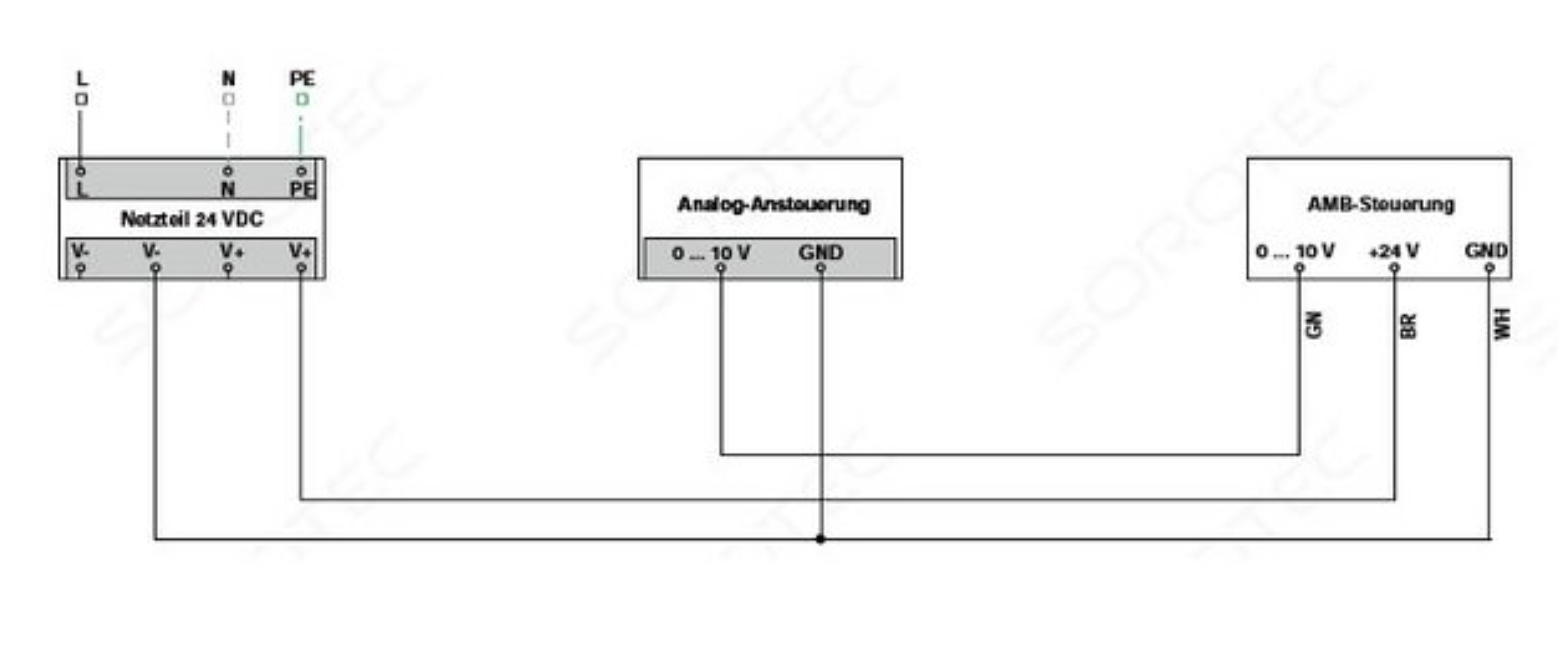
I've done a little drawing, so perhaps this will be of use to someone in the future...

Enjoy!
Edit: Changed image to the real one!