Mesh bed compesation seems not to work properly
-
Good morning, in my print I use an awful bed plate, I know it but at now I have no money to buy a good one. It is very distorted and when it's heated the distortion still increase...I've tried all my best to adjust the screw (using G32), and I've also made a compenstaion mash (G29 S0). There are still wide areas of the plate when the compensation mesh seems not to work properly. In that areas I see the Z axis moving during the print but the compensation is not enough infact in some areas the nozzle is too high from the plate and in other it's too close and the extruder loose steps because the filament doesn't flow properly.
I repeat, I know the bed plate is awful but I'm wondering if there could be a way to improve the compensation mesh to get a better result waiting for the moment to change the plate.
Here's my config,g:cacl310; Configuration file for Duet WiFi (firmware version 3) ; executed by the firmware on start-up ; ; generated by RepRapFirmware Configuration Tool v3.1.4 on Sun Nov 01 2020 08:34:36 GMT+0100 (Ora standard dell’Europa centrale) ; General preferences G90 ; send absolute coordinates... M83 ; ...but relative extruder moves M550 P"DragonCore" ; set printer name M669 K1 ; select CoreXY mode ; Network M552 S1 ; enable network M586 P0 S1 ; enable HTTP M586 P1 S1 ; enable FTP M586 P2 S1 ; enable Telnet ; Drives M569 P0 S1 ; physical drive 0 goes backwards M569 P1 S1 ; physical drive 1 goes backwards M569 P2 S0 ; physical drive 2 goes backwards M569 P3 S0 ; physical drive 3 goes backwards M569 P4 S0 ; physical drive 4 goes backwards M584 X0 Y1 Z2 E3 ; set drive mapping M350 E16 I0 ; configure microstepping without interpolation M350 X16 Y16 Z16 I1 ; configure microstepping with interpolation M92 X79.8 Y79.8 Z2376.48 E415 ; set steps per mm M566 X1200.00 Y1200.00 Z12.00 E6000 ; set maximum instantaneous speed changes (mm/min) #################################### M203 X18000.00 Y18000.00 Z360.00 E5000.00 ; set maximum speeds (mm/min) ############################ M201 X9000.00 Y9000.00 Z100.00 E5000.00 ; set accelerations (mm/s^2) ############################### M906 X1200 Y1200 Z900 E500 I30 ; set motor currents (mA) and motor idle factor in per cent ###################################e M84 S30 ; Set idle timeout ; Axis Limits M208 X0 Y-25 Z0 S1 ; set axis minima ################################ M208 X310 Y310 Z350 S0 ; set axis maxima ######################################### ; Endstops M574 X1 S1 P"xstop" ; configure active-high endstop for low end on X via pin xstop M574 Y1 S1 P"ystop" ; configure active-high endstop for low end on Y via pin ystop M574 Z1 S2 ; configure Z-probe endstop for low end on Z ; Z-Probe M558 P9 C"^zprobe.in" H5 F300 T6000 ; set Z probe type to bltouch and the dive height + speeds G31 P500 X-26.116 Y29.279 Z1.26 ; set Z probe trigger value, offset and trigger height ############################################### M557 X5:280 Y70:330 P20 ; define mesh grid ##################################################### M557 X5:280 Y70:330 P20 ; Heaters M308 S0 P"bedtemp" Y"thermistor" T100000 B4092 ; configure sensor 0 as thermistor on pin bedtemp M950 H0 C"bedheat" T0 ; create bed heater output on bedheat and map it to sensor 0 M307 H0 B0 S1.00 ; disable bang-bang mode for the bed heater and set PWM limit M140 H0 ; map heated bed to heater 0 M143 H0 S120 ; set temperature limit for heater 0 to 120C M308 S1 P"e0temp" Y"thermistor" T100000 B4725 C7.060000e-8 M950 H1 C"e0heat" T1 ; create nozzle heater output on e0heat and map it to sensor 1 M307 H1 B0 S1.00 ; disable bang-bang mode for heater and set PWM limit M143 H1 S285 ; set temperature limit for heater 1 to 280C ; Fans M950 F0 C"fan0" Q2000 ; create fan 0 on pin fan0 and set its frequency M106 P0 S0 H-1 ; set fan 0 value. Thermostatic control is turned off M950 F1 C"fan1" Q500 ; create fan 1 on pin fan1 and set its frequency M106 P1 S1 H1 T50 ; set fan 1 value. Thermostatic control is turned on M308 S4 Y"mcu-temp" A"MCU" ; configure sensor 3 as thermistor on pin e1temp for left stepper M308 S3 Y"drivers" A"Drivers" ; configure sensor 4 as temperature warning and overheat flags on the TMC2660 on Duet ; ============================================= ; = LED FAN = ; ============================================= M950 F11 C"exp.heater4" M106 P11 S0 ; Tools M563 P0 S"Master" D0 H1 F0 ; define tool 0 G10 P0 X0 Y0 Z0 ; set tool 0 axis offsets G10 P0 R0 S0 ; set initial tool 0 active and standby temperatures to 0C ; Miscellaneous M575 P1 S1 B57600 ; enable support for PanelDue M912 P0 S-2.45 ; calibrates CPU temp M501 ; load saved parameters from non-volatile memory ; ========================================================= ; = D R A G O N C O R E = ; ========================================================= ; ================== ; = VARIABLES = ; ================== global primingExtruderAmount=12 ; ================== ; = NOZZLES WIPING = ; ================== global XWipeEnterCoord=0 global YWipeEnterCoord=0 global XWipeStartCoord=38 global XWipeEndCoord=77 global XWipeFinalCoord=147 global YWipeFinalCoord=-25 ; ================== ; = FOR PA SETTINGS= ; ================== ;global g_pa_setting = 0.12 ; the current pressure advance setting ;global g_pa_increment = 0.02 ; the amount to increment the pressure advance setting ;global g_pa_layer_count = 20 ; For 0.2mm layer height the number of layers to count to cause the incrementing of the pressure advance setting ;global g_pa_layer_count = 10 ; For 0.6mm layer height the number of layers to count to cause the incrementing of the pressure advance setting ;global g_pa_layer_count = 30 ; For 0.1mm layer height the number of layers to count to cause the incrementing of the pressure advance setting ;global g_pa_layer_counter = 0 ; the current layer count ;M572 D0 S{global.g_pa_setting} ; ================== ; = SCREWS POINTS = ; ================== M671 X5:310:100:5 Y310:310:5:5 P0.5 ; point1 (5,320), point2 (320,320), point3 (320,5), point4 (5,5) ; ==================== ; = FILAMENT SENSOR = ; ==================== M591 D0 P1 C"e0stop" S1 ; ================= ; = ACCELEROMETER = ; ================= M955 P0 C"spi.cs4+spi.cs3" I50 ; ================== ; = INPUT SHAPING = ; ================== M593 P"zvddd" F49 ; ====================== ; = POWER FAILURE = ;======================= M911 S21 R23 P"M913 X0 Y0 G91 M83 G1 Z3 E-5 F1000" ; power failurehere's the beg.g:
; bed.g

G28 XY; home
G28 Z

M401 ; deploy Z probe

G30 P0 X10 Y320 Z-99999 ; probe near an adjusting screw
G30 P1 X155 Y320 Z-99999 ; probe near an adjusting screw
G30 P2 X285 Y320 Z-99999 ; probe near an adjusting screw
G30 P3 X285 Y70 Z-99999 ; probe near an adjusting screw
G30 P4 X155 Y70 Z-99999 ; probe near an adjusting screw
G30 P5 X25 Y70 Z-99999 S-1; probe near an adjusting screw and report adjustments needed

M402 ; retract probe
and here's the Macro I wrote for the mesh compensation:
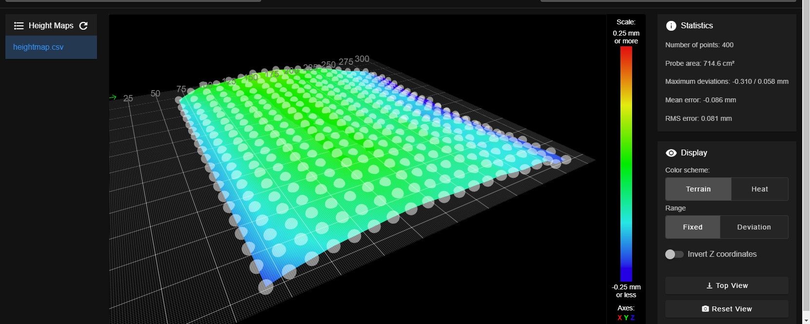
G28 XY ;Home XY
G1 X165 Y165 ; Move Probe to middle of bed
G30 ; Do a single probe
G29 S0 ; create height map
And here's the disater:
As leveling sensor I use and Inductive VINDA
Is there something that could be done?
Thanks!
-
@TheDragonLord
Is there something that could be done?
Looks like you are plagued with a sagging gantry. What you call a disaster describes a bed which is pretty flat over Y. Even over X, you just have these blue blips on the left and right. Without using mesh compensation, you should be able to print a decent first layer all over the green area of the bed. If that doesn’t work, level the bed manually and try again.
By this approach, you get an idea which areas of the map represent the bed’s surface - and which values originate from other parts of your mechanics. These issues then have to be fixed.
-
@infiniteloop thanks,the issues can't be fixed because they are related to the bed plate deformations. When it heats up the center of the bed itself almost "pops up"...as I told I know I'll have to change it but I just would like to know if there's a way to improve the compensation in the meanwhile, I don't know,maybe changing the number of the probing points for the mesh or changing some other parameter, I don't know...It sound strange to me that even if the Z moves to compensate during the print there are areas in which the compensation works properly and others in wich it doesn't...it looks like during the probing for the mesh definitions not all the heights for the various points are taken correctly...
-
@TheDragonLord
When it heats up the center of the bed itself almost "pops up"...
Understood.
even if the Z moves to compensate during the print there are areas in which the compensation works properly and others in wich it doesn't...
Can you describe where these areas are located? Do they match the blue portions of your map, or are they unrelated?
it looks like during the probing for the mesh definitions not all the heights for the various points are taken correctly...
Then, please post a map generated with a cold (i.e. unheated) bed for comparison. Maybe the VINDA is somehow affected by the heat, the electric field of the heater or something else?
-
@infiniteloop said in Mesh bed compesation seems not to work properly:
@TheDragonLord
When it heats up the center of the bed itself almost "pops up"...
Understood.
even if the Z moves to compensate during the print there are areas in which the compensation works properly and others in wich it doesn't...
Can you describe where these areas are located? Do they match the blue portions of your map, or are they unrelated?
it looks like during the probing for the mesh definitions not all the heights for the various points are taken correctly...
Then, please post a map generated with a cold (i.e. unheated) bed for comparison. Maybe the VINDA is somehow affected by the heat, the electric field of the heater or something else?
the compensation doesn't work well in the front part of the bed particularly in the front left side the nozzle is almost scratching the plate...theoretically the vinda shouldn't be affected by none of the effects you described...at now I can't make a "cold" mesh because I've just started a new print...
-
@TheDragonLord
particularly in the front left side the nozzle is almost scratching the plate...
Ouch! – That seems not to correspond with your height map. Let’s see the results of the „cold mesh“ (nice term btw) after your current print.
-
@TheDragonLord It's not esay to tell from the heightmap screenshot where (0, 0) actually is, but it also looks like you have about 50mm of the bed not actually mapped, I wonder if that is part of the problem.
Perhaps you could post a "top down" screenshot of the heightmap (or the actual csv file), so we can check.
-
@gloomyandy said in Mesh bed compesation seems not to work properly:
@TheDragonLord It's not esay to tell from the heightmap screenshot where (0, 0) actually is, but it also looks like you have about 50mm of the bed not actually mapped, I wonder if that is part of the problem.
Perhaps you could post a "top down" screenshot of the heightmap (or the actual csv file), so we can check.
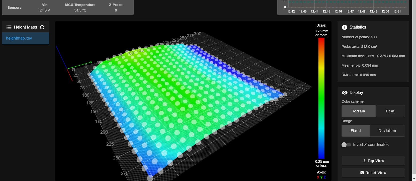
Here's a better screnshot and the height mp file:

The "un-probed 50mm" you mentioned are in the right side because my Vinda is mounted in the left side of the nozzle and I don't have enough space in the right side of the frame to allign the Vinda with the right limit of the plate but the nozzle mainly "scratches" in the left side
-
@infiniteloop Here are the cold and hot height maps...honestly I don't understand because now they look almost the same (last time I've made a "cold mesh" was few months ago just after mounting the brand new bed plate)....maybe it means that the bed plate now is definitely distorted even when it's cold...!
Hot height map:
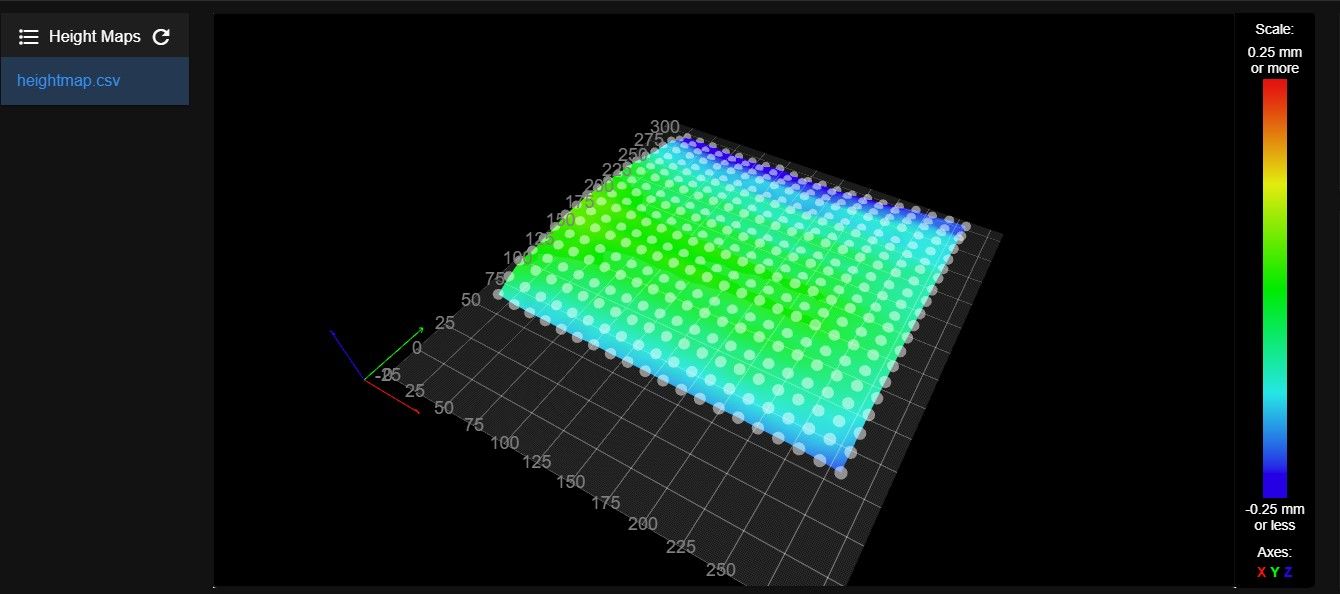
hot_heightmap.csvCold height map:
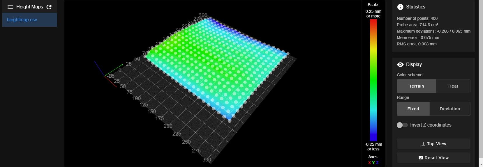
cold_heightmap.csv -
@TheDragonLord Unless there is something odd going on with that heightmap display it is missing a large strip from -25 up to about 50 or 60. So that means you will have no heightmap correction for the front part of your bed. Earlier you said that the main problem was "particularly in the front left side" where exactly was the print? As you mentioned it is also missing a strip down the right side of the bed. That missing strip at the front of the bed seems pretty large to me is your probe really offset by that much? It might help if you post a picture of your print head.
-
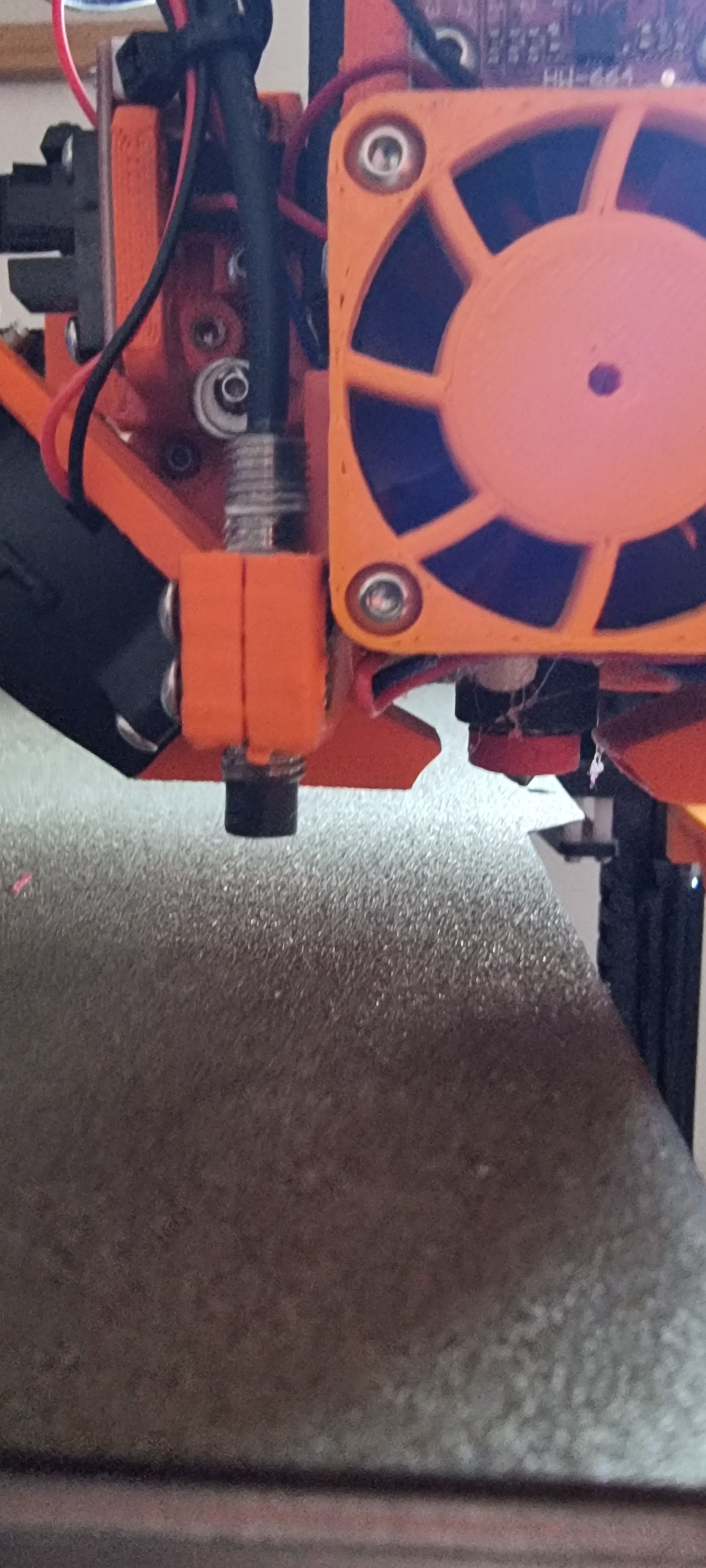
@gloomyandy hi, here's some photos of my print head, the first one shows the reason for the missing right part...about the missing of the front part for me it sounds strange to me because with the setted offsets the vinda probes the bed not so close to the edge but even not so far...the probe offsets from the nozzles are correct as well as the offsets for the 0,0 corners related to the endstops...what have I setted wrong?!
Right side:
Front probing distance:

Print head:

Probe offsets from nozzle and grid mesh:
M558 P9 C"^zprobe.in" H5 F300 T6000                    ; set Z probe type to bltouch and the dive height + speeds
G31 P500 X-26.116 Y29.279 Z1.26                           ; set Z probe trigger value, offset and trigger height
M557 X5:280 Y70:330 P20
bed.g:
G30 P0 X10 Y320 Z-99999 ; probe near an adjusting screw
G30 P1 X155 Y320 Z-99999 ; probe near an adjusting screw
G30 P2 X285 Y320 Z-99999 ; probe near an adjusting screw
G30 P3 X285 Y70 Z-99999 ; probe near an adjusting screw
G30 P4 X155 Y70 Z-99999 ; probe near an adjusting screw
G30 P5 X25 Y70 Z-99999 S-1; probe near an adjusting screw and report adjustments needed
I think that maybe my mistake could be here:
M557 X5:280 Y70:330 P20With the Y70 but if I set it lower than 70 the vinda stays outside the plate in front of it and, of course, the nozzle crashes the bed....
-
@TheDragonLord said in Mesh bed compesation seems not to work properly:
G31 P500 X-26.116 Y29.279 Z1.26
I don't think this is correct. Your probe seems to be in front and to the left of the nozzle in which case both offsets should be negative. See: https://docs.duet3d.com/en/User_manual/Connecting_hardware/Z_probe_testing#measuring-probe-x-y-offset.
-
@gloomyandy oh my......you're definetely right!!!! Thanks!!!
-
@gloomyandy said in Mesh bed compesation seems not to work properly:
@TheDragonLord said in Mesh bed compesation seems not to work properly:
G31 P500 X-26.116 Y29.279 Z1.26
I don't think this is correct. Your probe seems to be in front and to the left of the nozzle in which case both offsets should be negative. See: https://docs.duet3d.com/en/User_manual/Connecting_hardware/Z_probe_testing#measuring-probe-x-y-offset.
Here's my new mesh:
Of course correctly setting the probe offset has "transferred" the missing-probed-areas from the front to the rear but to solve this I can reduce the Y dimension for the printer from 310 to 285, it's not a big problem....in my next print I'll see if the compensation now will works properly but I have no doubt it will...
Thanks again! -
Thanks to the help now the bed compensation works a lot better! The post could be changed as "solved" (I don't see any option to changed by myself)
Thanks!
-
 undefined Phaedrux marked this topic as a question
-
undefined Phaedrux has marked this topic as solved