Issue with Z-probe and G29/G32
-
Hi all,
I’m having some trouble getting the bed leveled on a custom build I’m finishing and I’m hoping someone can point me in the right direction. First, some background on the printer. It’s a CoreXY (twisted belt) tool changer with three independent Z motors for a 0.25” (6.35 mm) thick cast Al bed. The bed is 12” x 12” (350 x 350 mm), 250 mm x 250 mm printable area, and total travels are 270 mm x 340 mm x 275 mm. The Z screws are located at the front right/left and center back. Duet 3 Mini 5+ on firmware V3.3. Micro switches for X and Y limit, no Z limit. I’m using an E3D tool changer and the Z-probe is the micro switch that’s included. (It’s bolted to the back of the tool changer face plate). Finally, this is my second printer with the Duet. I fitted the Mini 5+ to an old printer about a year ago to get familiar with everything.
The first problem I’m having it that I can’t get the bed to level itself via G32. To check the results, I’ve attached a .0005” (.012 mm) dial test indicator and jog it along the bed with a zero set at point 3. After running G32 a few times, the results for leadscrew adjustments converge on negative values of about the same magnitude. According to a post I found, this indicates that the bed isn’t perfectly flat, which is expected based on the stated flatness tolerance of the Al. When I verify with the indicator by checking the bed near the leadscrews, I see deviations of +.011” and +.020” at points 2 and 1, respectively (.25 and .5 mm). These deviations seem to be consistent.
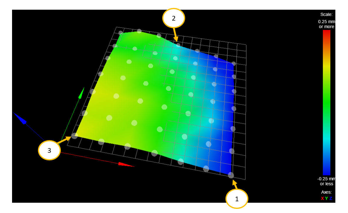
The second problem I’m having is that the height map that results from G29 are inaccurate. I’m running a 7x7 grid from 20:240 on X and Y. I started with manually leveling the bed with the dial test indicator by putting the tip near the probe point (1, 2, and 3) and moving the screw until I read a 0. After a few iterations of this, the “probe” points always returned to 0 on the indicator and when sweeping across the bed, the needle stayed within +.010” (+.25 mm) of the datum. The image below is the result of the G29 meshing. I believe it measures and tries to apply a clockwise roll around the Y-axis. Similarly, when I run G29 after a few runs of bed.g, the mesh is basically level despite measured offsets of .020” and .011” at points 1 and 2.
I think these point to a twist in the gantry or frame somewhere, but I’m not sure. Basically, it looks like the Z probe measures a larger value at high X points, and lower values and small X points. I’ve played the G30 H parameter in bed.g, and while it helps somewhat with the first problem, the height offset isn’t applied when running G29. I’m wondering if anyone sees anything I may have missed or how I can solve this.
Thank you for the help!

config.g
 ; Configuration file for Duet 3 Mini 5+ (firmware version 3.3)
; executed by the firmware on start-up
;
; generated by RepRapFirmware Configuration Tool v3.3.1 on Fri Aug 27 2021 14:17:25 GMT-0600 (Mountain Daylight Time)
; current as of 11-12-2022

G90                                          ; send absolute coordinates...
M83                                          ; ...but relative extruder moves
M550 P"MiniTC"                 ; set printer name

; Network
M551 P"GoodHouse!"                           ; set password
M552 S1                                      ; enable network
M586 P0 S1                                   ; enable HTTP
M586 P1 S0                                   ; disable FTP
M586 P2 S0                                   ; disable Telnet

; Drives
M569 P0.0 S0                                 ; physical drive 0.0 goes backwards - 'X'
M569 P0.1 S0                                 ; physical drive 0.1 goes backwards - 'Y'
M569 P0.2 S1                                 ; physical drive 0.2 goes forwards - Z - Front Right
M569 P0.3 S0                                 ; physical drive 0.3 goes backwards - Z - Rear
M569 P0.4 S1                                 ; physical drive 0.4 goes forwards - Z - Front Left
M569 P0.6 S1                                 ; physical drive 0.5 goes forwards - B - Tool Changer

M669 K1;			l CoreXY

; Axes
M584 X0.0 Y0.1 Z0.2:0.3:0.4 B0.6				; set drive mapping
M350 X16 Y16 Z16 B8 I1               	    	; configure microstepping with interpolation
M92  X160.00 Y160.00 Z1600.0 B91.022  	        ; set steps per mm
M566 X900.00 Y900.00 Z900.0 B2   		    	; set maximum instantaneous speed changes (mm/min)
M203 X30000.00 Y30000.00 Z1000.00 B10000 		; set maximum speeds (mm/min)
M201 X2000.00 Y2000.00 Z500 B500          		; set accelerations (mm/s^2)
M906 X1000 Y1000 Z400 B1200 I30          	    ; set motor currents (mA) and motor idle factor in per cent

; 	Extruders - definitions are for T0:T1:Tn
M569 P20.0 S1                                 ; T0 drive on board 20.0 goes forwards
M584 E20.0					; Set drive mapping - T0
M350 E16					; Micro Stepping - T0
M92 E690					; Steps / mm
M566 E300        		    ; set maximum instantaneous speed changes (mm/min)
M203 E7200	; set maximum speeds (mm/min)
M201 E600           ; set accelerations (mm/s^2)
M906 E1200 I30          	        ; set motor currents (mA) and motor idle factor in per cent
M84 S30                                          			; Set idle timeout

; independant leveling
M671 X272.8:125.8:-20 Y-18.5:272.8:-21 S10	; location of leadscrews | Front right - rear - front left

; Mesh leveling
M557 X20:240 Y20:240 P7:7		; define mesh grid

;extruders
M84 S30                                         ; Set idle timeout

; Axis Limits
; 	this sets the printer origin at about (26, 27) when measured from the front left corner of the Al plate
M208 X-5 Y-42 Z0 B-180 S1                        ; set axis minima
M208 X265 Y298 Z275 B180 S0                      ; set axis maxima

; Endstops
M574 X1 S1 P"io1.in"                         ; X endstop on io1 in - invert signal with !
M574 Y2 S1 P"io2.in"                         ; Y endstop on io2 in - invert signal with !
M574 Z0										 ; No Z-end stops

; Z-probe
M558 P8 C"io3.in" H10 R0.5 F500:120 T10000	; set z probe type to switch on io2.in | "feed plane" is ~10mm
G31 Z-0.513									; probe trigger height

; Heaters
;     Bed
M308 S0 P"temp0" Y"thermistor" T100000 B3950 ; configure sensor 0 as thermistor on pin temp0 - Bed heater
M950 H0 C"out0" T0                           ; create bed heater output on out0 and map it to sensor 0
M307 H0 B0 R0.794 C348.7 D5.72 S1.00     	 ; M303 results for bed heater - 11/4/2022
M140 H0                                      ; map heated bed to heater 0
M143 H0 S110                                 ; set temperature limit for heater 0 to 110C

G4 S2;  Wait for tool board to start up


; Tool 0 - CAN address 20
; 	T0 Heater and thermistor
M308 S1 P"20.temp0" Y"thermistor" T100000 B4138 ; configure sensor 1 as thermistor on pin temp1 - Extruder heater
M950 H1 C"20.out0" T1                           ; create nozzle heater output on out1 and map it to sensor 1
M307 H1 B0 R3.401 C149.7 D5.31 S1.00	  	    ; M303 results for T0 Heater - 11/5/2022
M143 H1 S290
;	T0 Fans
	; Print fan
M950 F0 C"20.out2" Q500                         ; create fan 0 on pin out5 and set its frequency
M106 P0 S0 H-1                               ; set fan 0 value. Thermostatic control is turned off
	; tool 0 ext fan
M950 F1 C"20.out1" Q500                         ; create fan 1 on pin out6 and set its frequency
M106 P1 S.5 H1 T45                           ; set fan 1 value. Thermostatic control is turned on


; tool 0
M563 P0 D0 H1 F0
G10 P0 R190 S235                              ; set initial tool 0 active and standby temperatures
G10 P0 X0 Y-47.8 Z-7.58

; Miscellaneous
M575 P1 S1 B57600							; start serial for panel due
;M556 S50 X-1.5 P1					        ; axis skew
homeall.g
; homeall.g- 10/21/2022
G91;
G01 H1 X-300 Y400 F3000
G01 H1 X-300
G01 H1 Y400
G1 X4 Y-4 F600           ; move away from the endstops
G1 H1 X-10              ; fine home X
G1 H1 Y10              ; fine home Y

G90;

; Zhome to follow
G01 X125 Y125 F10000; move to center of the bed
G30

G01 X10 Y10 Z15
bed.g
M561 ; clear any bed transform G28 ; home G30 P0 X240 Y20 Z-9999; H-0.375; H-.0397; G30 P1 X125 Y250 Z-9999; H-.25; H-.0475 G30 P2 X10 Y20 Z-9999 S3; H-.0313; G28 Z; G01 Z15 F1000; Move to convient location G01 X10 Y50 F10000; -
@Alex-0 said in Issue with Z-probe and G29/G32:
I think these point to a twist in the gantry or frame somewhere
Yes that sounds likely from your description.
@Alex-0 said in Issue with Z-probe and G29/G32:
G28 Z;
What's in your homez.g?
-
@Phaedrux Thanks for the reply. Here's my homez.
G01 X125 Y125 F10000; move to center of the bed
G30

G01 X10 Y10 Z15
I don't suppose there's any way to work around the twist or a simple way to locate it?
-
I haven't seen your printer, but usually a disassembly and careful reassembly with a square and flat surface could be enough to correct the error.
Also check for tilt/rotation on the print head due to it's own weight.
-
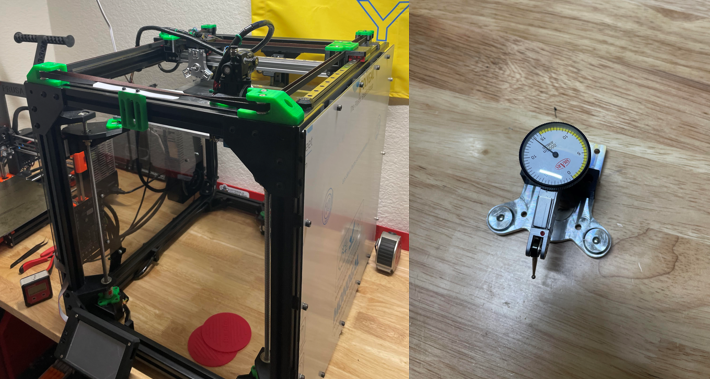
Here’s a photo of the printer. It’s mostly PETG prints and 3030 extrusions, all milled to ± .005”. I assembled the frame on the bench it currently rests on (1” butcher block surface) and checked throughout with a 12” combination square. My next step would be to assemble it on a surface plate which I feel is a bit overkill. Also, I’m not all that eager to do a complete rebuild without having a means of ensuring this problem won’t crop up again.
@Phaedrux said in Issue with Z-probe and G29/G32:
Also check for tilt/rotation on the print head due to it's own weight.
That’s a non-issue as I don’t have a print head installed. I attached my dial test indicator to a tool changer face plate and have been using that to measure. The tip of the indicator is ~30mm in front of the probe.

-
I’d like to update this thread in case it can help anyone out.
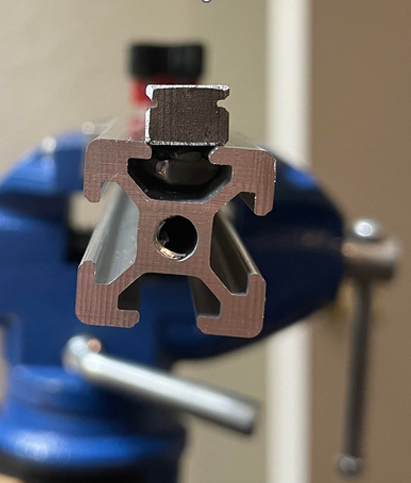
I went ahead and started a careful reassembly per Phaedrux a few weeks ago. In doing so I discovered that the 2020 extrusion I was using for the X gantry was basically worthless. The edges on the 2020 are chamfered which makes the channel just about as wide as the linear rail. What I think happened was the rail wasn’t exactly aligned and it ended up slightly diagonal to the long axis. Tightening the bolts forced the rail to match the ‘contour’ of the beam and that’s where the twist came from. Those chamfers weren’t captured in the solid model and even with alignment tools, it was nearly impossible to get the rail seated properly. I’ve exaggerated that in the picture below. My solution to this was to machine a new gantry beam from Al and that seems to have solved the problem. When I run a bed mesh and check with an indicator, I’m within .004” (.1 mm).
I know most people don’t have access to a Bridgeport so this route isn’t the most realistic, but my big take away is to keep an eye on the extrusion profile when dealing with smaller parts.
Thanks for the help @Phaedrux!

-
Good catch ... and yes, the linear rail is clearly wrong for that extrusion. Good job machining your own gantry !
-
 undefined Phaedrux marked this topic as a question
-
 undefined Phaedrux has marked this topic as solved