Milling motor control - Duet3/PWM Converter
-
Despite my efforts in getting this to work, I've hit a bit of a snag.
I have a Duet3 MB6HC with a 0-10V PWM converter to control my Sorotec 1000 PV-ER milling motor (MM), and I'm pretty sure i've got it connected properly, and I've tested the cables from the source to the milling motor's digital interface plug for continuity, but the MM is permanently on, when it and the control board are powered up.
There are three (relevant) connectors between the control board/PWM converter and the MM, as follows (in laymen's terms):
-
One pin is provided with a voltage from the PSU to disable the manual speed controller on the MM (brown coloured wire).
-
A second pin is provided with the signal input from the PWM converter to control the speed of the MM (white coloured wire).
-
A third pin is the ground connector (blue coloured wire).
I've tested the brown wire and there is a 24V supply to the plug of the MM (the supply must be between 8 and 53V) and this, in theory, should prevent the MM from being turned on without a direct command from the gcode file (i.e. M3).
The control board is powered from the mains (via a PSU) with a passthrough power cable for the MM (like a PC with an power outlet for a monitor), so when the power socket is switched on, both the control board and MM are powered up. This is by design as the MM shouldn't start up without the GCode command, but it does (don't worry, I checked it safely!)
The milling motor works as it should when the digital interface cable is not connected, i.e. the speed control knob controls the speed of the MM, but what is interesting is that when the digital interface cable is connected to the MM, it runs at it's lowest speed and changing the speed control knob has no effect on the speed.
Here's a diagram of how everything is connected:
Image deleted
And here's the relevant part of the config file:
; Sorotec spindle configuration
M950 R0 C"vfd" L0:25000 Q1000	; create spindle with index 0
M563 P0 S"Sorotec" R0		; create tool 0 with spindle 0 and name it "Sorotec"
T0				; select tool 0
So, does anyone have any idea why the MM is aways on, please, and why it can't be controlled from the command line, to either turn it off/on or change the speed?
Thank you.
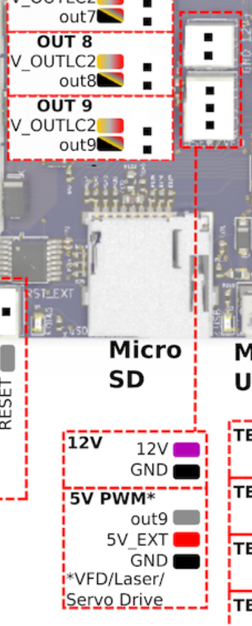
EDIT: I forgot to add that the PWM converter is connected to this header:

-
-
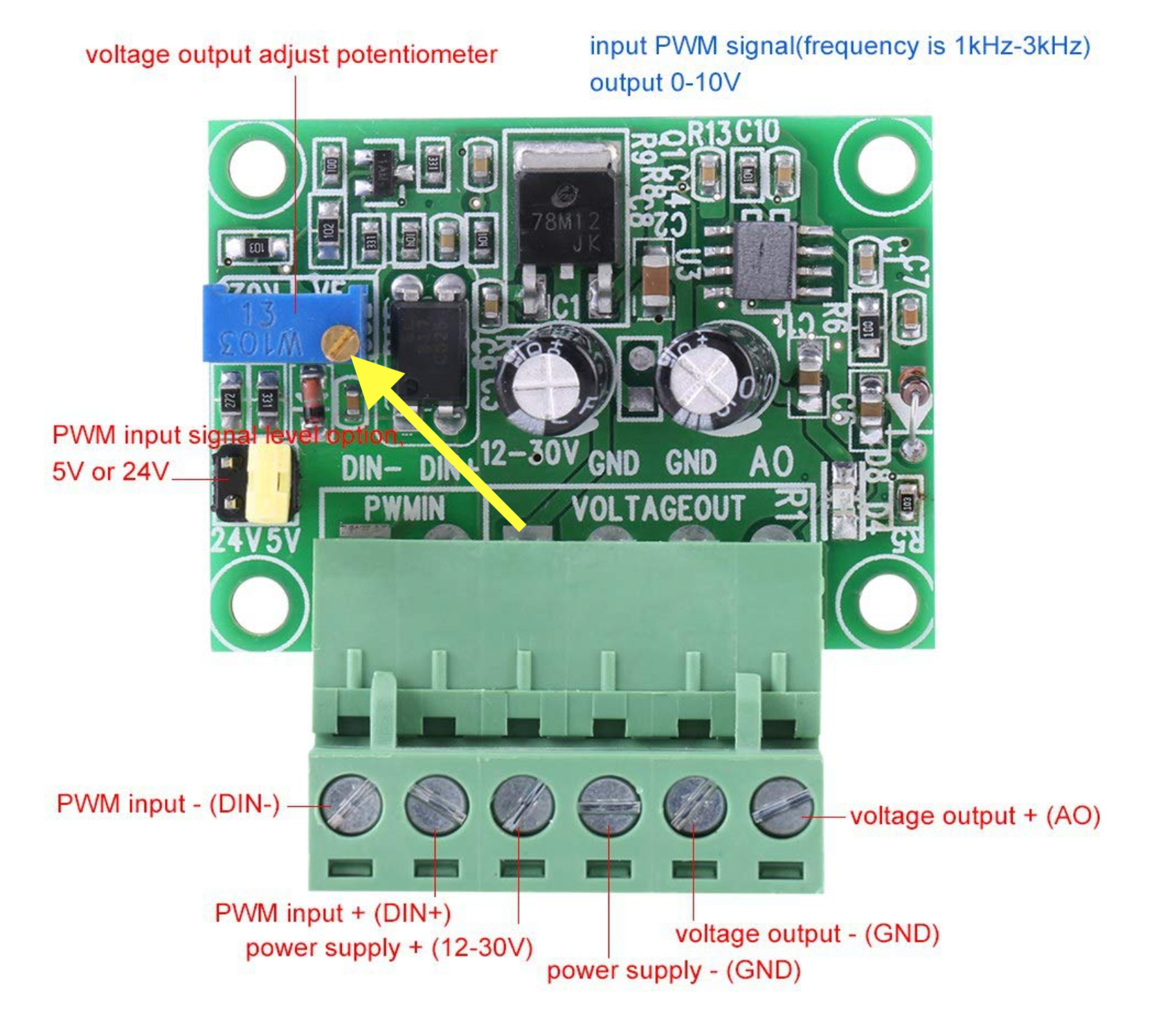
@Nightowl which PWM converter do you have? There are two types commonly available; one is OK, the other is not because of a stupid design fault on it. See https://docs.duet3d.com/User_manual/Machine_configuration/Configuration_CNC#connecting-a-spindle.
-
-
@Nightowl yes that's the correct one.
You appear to be using the 5V_PWM (aka Laser/VFD) output from the Duet to drive the PWM to voltage converter. In that case you should connect the PWM+ input of the converter to the out9 pin of that connector, and the PWM- input of the converter to the GND pin. This is because the out9 output on that connector is active high. The +5V pin is intended for powering small servos when they are attached to that connector.
-
This is a bit surprising. It seems the minimum speed of the milling motor is 4,000rpm and it will run at that speed when powered up, irrespective of whether the digital interface is used or not.
This might present me with a problem, but I think there's a way around it - but I might need help.
Presently, for the Makita palm router, I use the following code to configure it in the config.g file:
; Makita and relay configuration
M950 R0 C"out1+out7" L0:18000	; enable router relay on out7
M563 P0 S"Makita" R0		; assign spindle 0 to tool 0 and name it Makita
T0				; select tool 0
...which works well. It essentially turns the Makita on via this Keene relay.
I had planned to use the following code for the Sorotec:
; Spindle configuration
M950 R0 C"vfd" L0:25000 Q1000	; create spindle with index 0
M563 P0 S"Sorotec" R0		; create tool 0 with spindle 0 and name it "Sorotec"
T0				; select tool 0
...but I think I will have to do one of two things.
Firstly, keep the code as it is and assign different tool numbers, but I'm not sure if/how I could activate (essentially) two tools at the same time.
Secondly, combine the code into one configuration 'group', but I'm not sure there is any benefit in this, over the first option.
Has anyone got any ideas, please?
Thanks
-
@Nightowl could you not add an extra relay to control the power and then add another output on the M950? like you have your mikita
-
That's what I was thinking. As I see it, any M3 command would need to 'operate' the relay (as it currently does for the Makita) and the Snnnn part to control the speed.
I'm just not sure how to incorporate the code to make that happen.
-
@Nightowl said in Milling motor control - Duet3/PWM Converter:
; Spindle configuration
M950 R0 C"vfd" L0:25000 Q1000 ; create spindle with index 0
M563 P0 S"Sorotec" R0 ; create tool 0 with spindle 0 and name it "Sorotec"
T0add another output to the M950, i.e.
M950 R0 C"vfd+out1" L0:25000 Q1000 ; create spindle with index 0
and wire the relay to out1 (you can adjust that as well).
M3 should activate that relay and M5 should turn it off. -
@Nightowl see the section on configuring spindles at https://docs.duet3d.com/en/User_manual/Reference/Gcodes#m950-create-heater-fan-spindle-or-gpioservo-pin for an explanation of the suggestion by @jay_s_uk.
-
I see! Thank you, @jay_s_uk
Of course, that makes sense. It's the same idea as for the Makita (apart from the pins) so if I used this, to configure the motor:; Spindle configuration M950 R0 C"vfd+out7" L0:25000 Q1000 ; create spindle with index 0 M563 P0 S"Sorotec" R0 ; create tool 0 with spindle 0 and name it "Sorotec" T0 ; select tool 0...that would get me to where I want to be, whilst keeping the relay on the existing pins.
That's brilliant, thank you so much!
-
Thanks, @dc42, I'll check it out

-
Just out of curiosity, how do I find out what the Q setting should be?
Is this information relative to the PWM controller, which is advertised as being 1kHz to 3kHz?
Thanks
-
@Nightowl its more relative to VFD
-
@Nightowl said in Milling motor control - Duet3/PWM Converter:
Just out of curiosity, how do I find out what the Q setting should be?
Is this information relative to the PWM controller, which is advertised as being 1kHz to 3kHz?Yes, use between 1000 and 3000.
-
Some progress!
Using the code below, I can now start/stop the motor with M3 Sn and M5 respectively, but I can't change the speed: it is constant at 4,000RPM, which suggests to me that the voltage required to change the speed isn't there. Possibly a fault with the PWM converter?
Here's the code:
; Milling motor and relay configuration M950 R0 C"vfd+out7" L0:25000 Q1000 ; enable router relay on out7 M563 P0 S"Sorotec" R0 ; assign spindle 0 to tool 0 and name it Sorotec T0 ; select tool 0 M5 ; ensure motor is turned off -
@Nightowl have you adjusted the variable resistor on the top? have you set the VFD up for PWM control? I had to change some of the registers on my VFD to use PWM rather than RS485
-
If you mean this one (arrowed), no I haven't:

I'm not using a VFD, though. Just following the instructions from the Ooznest website, the M950 guide and this document.
I've just noticed point 2 indicates the "5V/24V PWM input signal level option" should be set to 5V, so I'll need to check that...
-
One thing I've checked - very carefully, is the voltage across the 12V and GND connectors, adjacent to the 5V PWM connectors, on the Duet control board, and they're only providing 6V.
Also, the voltage across terminals GND and AO on the PWM board doesn't change when I adjust the motor speed (without the cable connected to the motor, so there's no load) from M3 S1000 to M3 S25000
That can't be right, surely?
Also, the jumper on the PWM board is set to 5V.
-
@Nightowl can you just confirm where the PWM is wired to on the duet board?
-
Certainly. The pins on the PWM board are connected to the Out9 VFD\Laser\Servo Drive header:
Port 1 (PWM in -ve) to 5V_Ext
Port 2 (PWM in +ve) to Out9
Port 3 (Power Supply 12-30V) to 12V
Port 4 (Power Supply GND) to GND
Port 5 (Voltage Out GND) to GND
Port 6 (Voltage Out +ve AO) to the motor plugThere is a loop between Ports 4 and 5, and this is also connected to the GND wire on the motor plug.
The third wire from the motor plug is connected to the PSU 24V +ve of the PSU.