Z 0 is positive
-
After a lot of tweaking this looks to be the best I can get.
Every adjustment of the plate (3-points) a G32 is a must, G30 and then G29.
Picture below is with 60°C heated bed.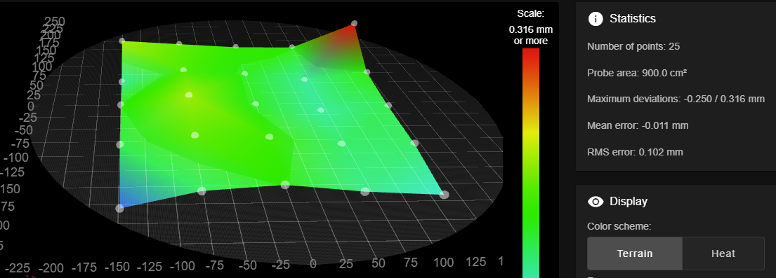
New 8mm thick fine milled cast aluminium plate Ø600mm, what can I expect to get in flatness?
Cheers
Bengt -
8mm thick fine milled cast aluminium plate Ø600mm, what can I expect to get in flatness?
That’s a good flatness, except of the front/left and rear/right - hmmm - "corners"?. For a Delta, a square grid as you’ve pictured is inappropriate. See
M557: Set Z probe point or define probing grid for details. Instead of defining the grid by X/Y, use R to set a radius. -
@infiniteloop
M557 R225 S75 it is -
M557 R225 S75 it is
Within the radius of 225 mm, some points cannot be reached by the probe without mechanical problems. These are not related to the bed but probably to issues with your motion system - to spot these areas, narrow-down your mesh to an S value of 20 or similar. In the next step, you can either solve the issues (but maybe these are inherent to a Delta) or minimise the probing radius in order to get a proper mesh which merely represents the surface of your bed, excluding other factors. Else, you can’t use the result for mesh bed levelling.
-
Can somebody explain what @infiniteloop is trying to say as I can not grasp this?
@infiniteloop said in Z 0 is positive:
For a Delta, a square grid as you’ve pictured is inappropriate
@infiniteloop said in Z 0 is positive:
Else, you can’t use the result for mesh bed levelling.
-
@tecno said in Z 0 is positive:
Can somebody explain …
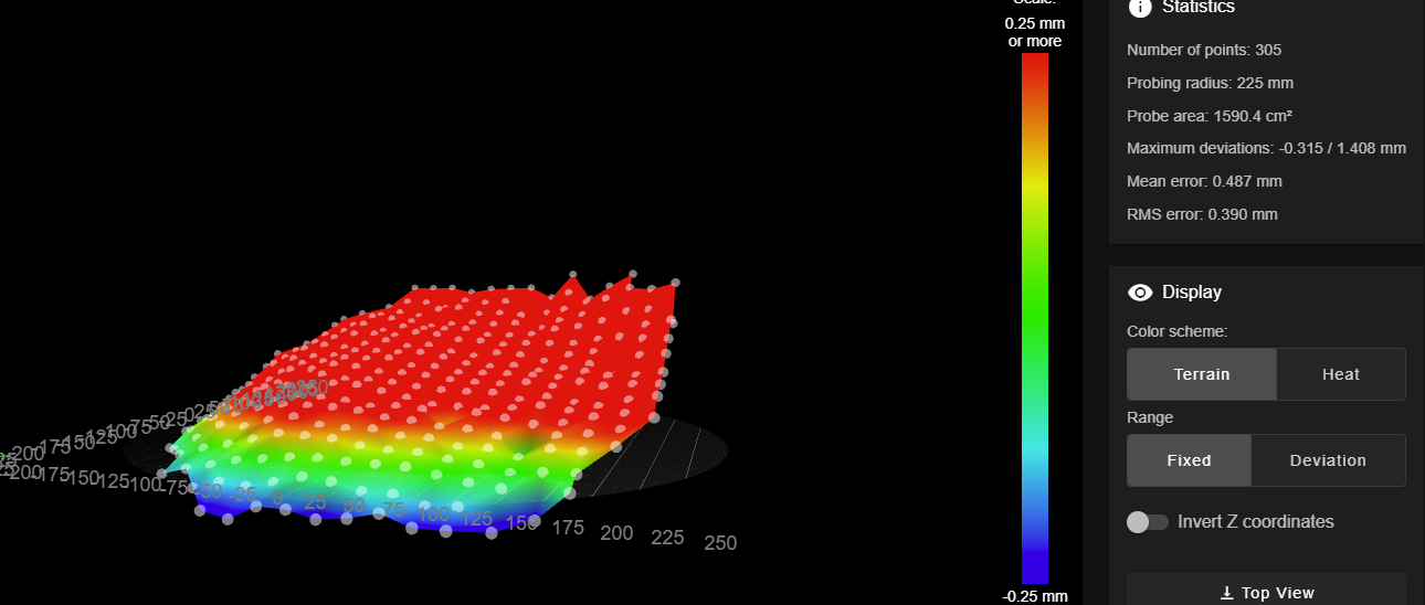
Sigh! Let me explain: you published this grid:
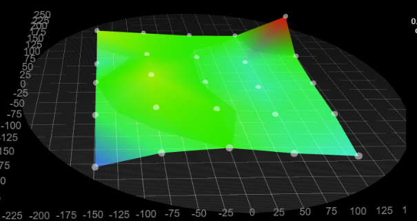
That grid is square - to be precise, it has a dimension of 5x5 points. This doesn't match your circular bed very well. That's why I think you might get a better picture using smaller S values, something like this:
M557 R225 S20OK, that's just to draw a better map of your casted print plate. It should cover a larger area than what you get with your current 75 mm raster. Had you ever followed the hint from my first post, you would know what I'm talking about

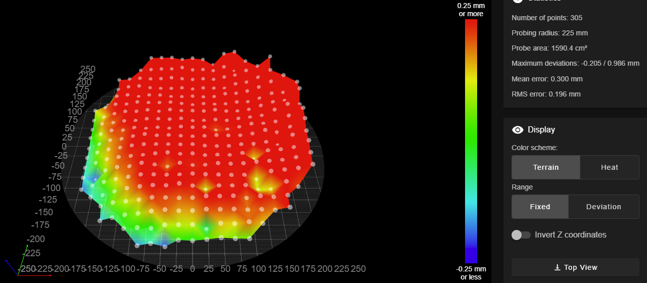
Now, let's talk about the mechanics:
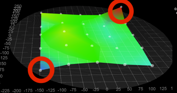
These two spots don't match the idea of a cast aluminum plate. There must be other reasons. If you follow my advice to generate a more narrow grid, chances are high that you will see even more of these "deviations".
Well, I think these "anomalies" at the edge of your printable area point at mechanical problems (or physical limitations) of your Delta …
… which puts our conversation into kind of a loop (as my nick name implies, I love these): after you have performed and published a better (more narrow) mesh, let's have a new look at my latest post (11.Dec 2022, 17:49).
-
-
@tecno said in Z 0 is positive:
Too many grid points; suggest increase spacing to 22.5mm
… or 25 mm - the important thing is to be able to observe the edge of the print bed. Alas, the new mesh looks somehow tilted: what makes it different from your first posted grid (other than mesh-spacing and heated vs. unheated bed)? Improper levelling? I can only guess, I'm no Delta expert at all

-
When in doubt, return to the basics.
https://docs.duet3d.com/en/User_manual/Machine_configuration/Configuration_linear_delta
https://docs.duet3d.com/en/User_manual/Tuning/Delta_calibration
-
@infiniteloop said in Z 0 is positive:
Improper levelling?
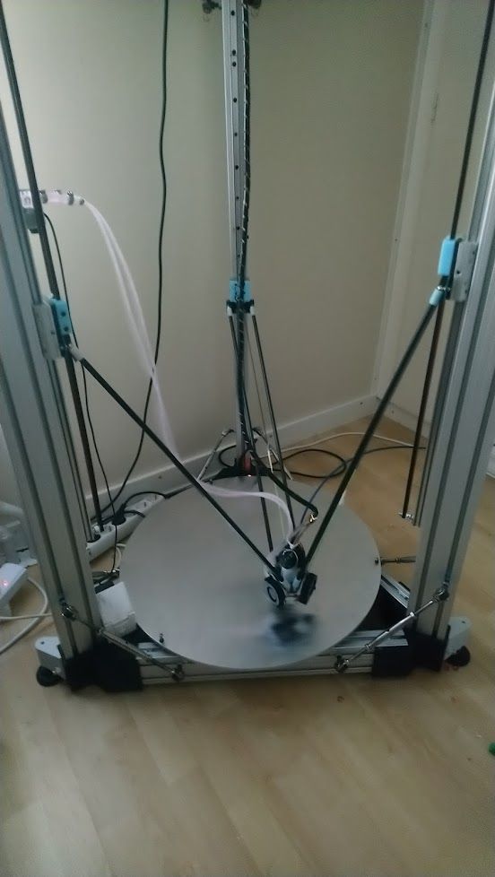
Looks like I need to tweak the thermal expansion move as I get different results each time.
The 3 balls on my bed adjusters need to move in another direction.So I will look at having 1 fixed and the two others moving freely in expansion direction from center of this aluminium bed. Any thoughts ?
-
@tecno said in Z 0 is positive:
1 fixed and the two others moving freely in expansion direction from center
Search out kinematic couplings.