Duet3D Logo Duet3D
    • Tags
    • Documentation
    • Order
    • Register
    • Login

    Emergency Push Button Pin Wiring

    Scheduled Pinned Locked Moved
    Duet Hardware and wiring
    4
    8
    239
    Loading More Posts
    • Oldest to Newest
    • Newest to Oldest
    • Most Votes
    Reply
    • Reply as topic
    Log in to reply
    This topic has been deleted. Only users with topic management privileges can see it.
    • SANJRundefined
      SANJR
      last edited by

      Hi I am planning to install a Emergency Push Button to the IO Connector of Duet 3D Mainboard 6HC.

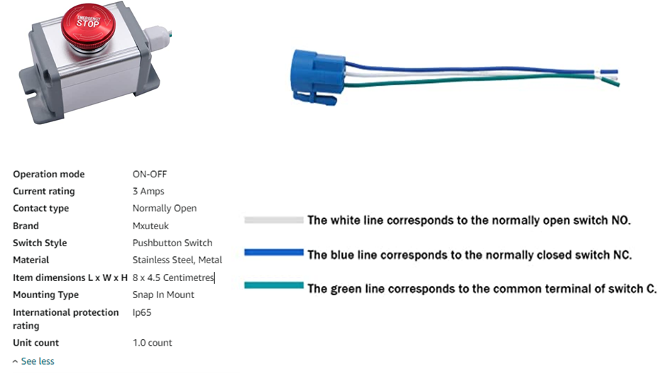
      The Push Button has three wires 1. NO (Normally Open) Wire 2. NC Wire 3. C Wire

      To what Pins should these wires be connected to Duet 3 IO Pin's?

      I am attaching the Specification Sheet and Wiring Photo of this Emergency Push Button for Reference
      Emergency Push Button.png

      jay_s_ukundefined 1 Reply Last reply Reply Quote 0
      • jay_s_ukundefined
        jay_s_uk @SANJR
        last edited by

        @SANJR normally closed and ground connected to groun and iox.in on the io connector

        Owns various duet boards and is the main wiki maintainer for the Teamgloomy LPC/STM32 port of RRF. Assume I'm running whatever the latest beta/stable build is

        SANJRundefined 2 Replies Last reply Reply Quote 0
        • SANJRundefined
          SANJR @jay_s_uk
          last edited by

          @jay_s_uk Hi Thanks for the reply
          Inference that NC Wire should be Connected to the GND Pin on the IO Connector. And the C and NO to which on the IO Connector to be connected?

          weed2allundefined 1 Reply Last reply Reply Quote 0
          • weed2allundefined
            weed2all @SANJR
            last edited by weed2all

            @SANJR C is common so it need to connect to Gnd, and NC pin to iox.in pin on duet board...the NO wire is left alone without connection

            https://www.thingiverse.com/weed2all/designs

            SANJRundefined 1 Reply Last reply Reply Quote 0
            • jens55undefined
              jens55
              last edited by jens55

              Since the next question will likely be 'what do I put into my config.g file?', this is my section for the emergency switch that I just installed after having procrastinated waay too long and having killed some expensive hardware. I am connected to the io7 port between ground and io7.in. It doesn't matter which wire goes to which of those two pins:

              ; Set up EMERGENCY STOP button
              M950 J1 C"IO7.in" ;creat input pin number 1 (J1) which is connected to the input of io7 connector
              M581 P1 T0 C0 S0 ; configure input pin number 1 (P1) .... T0 = emergency stop on trigger, C0 = allow trigger at any time (not just during print), S0 triggers on falling edge (NC)

              My emergency switch/button locks in the activated position. I have to twist it to let it pop back out to the 'run' position. Note that DWC gives you a message saying something about resetting the machine. You have to click on that message after the emergency stop is released in order to restart things.

              SANJRundefined 1 Reply Last reply Reply Quote 0
              • SANJRundefined
                SANJR @weed2all
                last edited by

                @weed2all Thanks for the Reply

                1 Reply Last reply Reply Quote 0
                • SANJRundefined
                  SANJR @jay_s_uk
                  last edited by

                  @jay_s_uk Thanks

                  1 Reply Last reply Reply Quote 0
                  • SANJRundefined
                    SANJR @jens55
                    last edited by

                    @jens55 Thanks for the Support

                    1 Reply Last reply Reply Quote 0
                    • First post
                      Last post
                    Unless otherwise noted, all forum content is licensed under CC-BY-SA