Building a CNC Pendant
-
I guess I have too much time on my hands because I'm designing and building a CNC pendant. I have three Duet3d-based systems in-house (a CNC, a 3d printer, a milling machine) and I really need a portable pendant.
Now that it's nearly finished I thought it might be time for some feedback

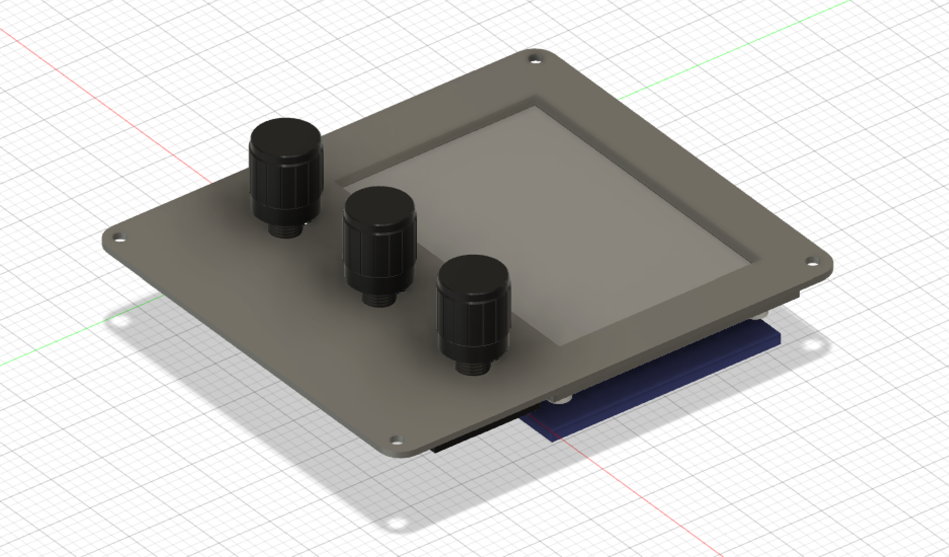
Here's a quick view of what I'm building.
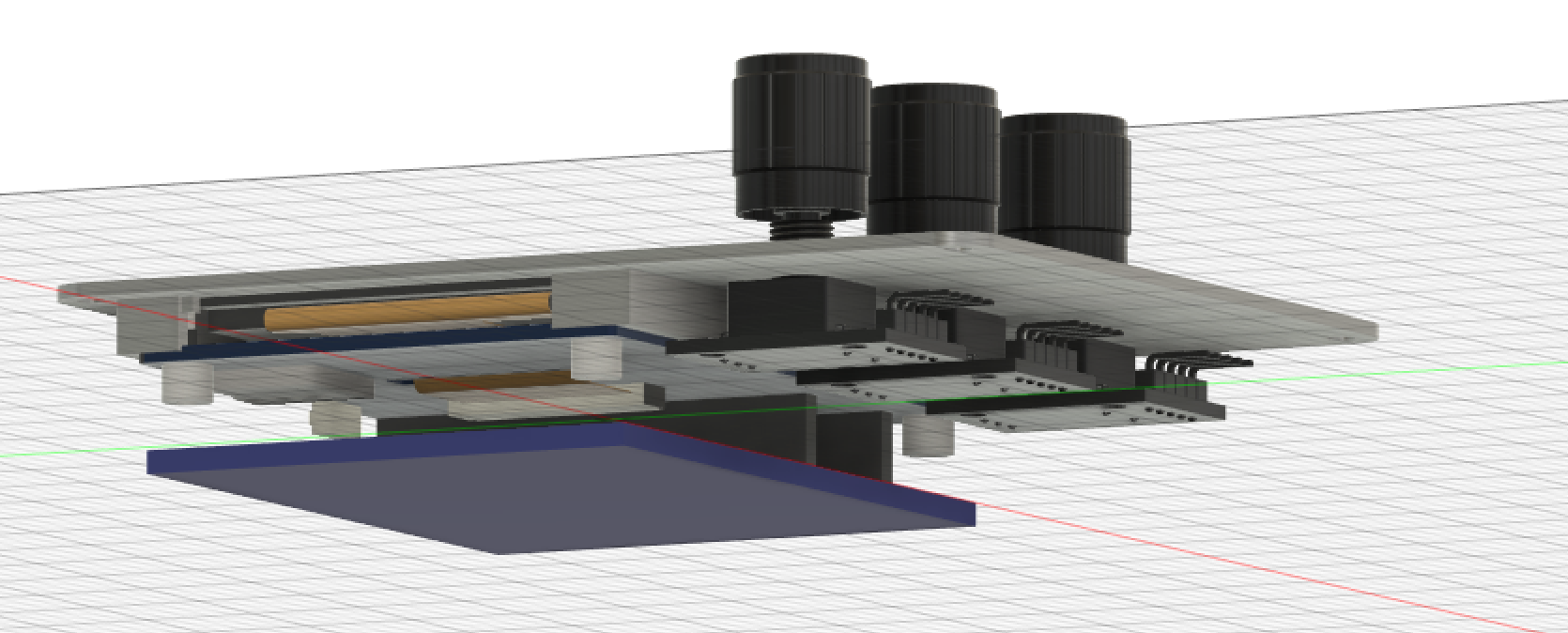
The case is 3d printed so pretty malleable. Each grid box is 1/2" (sorry not-metric) so the case is about 3.5"x4"x2".
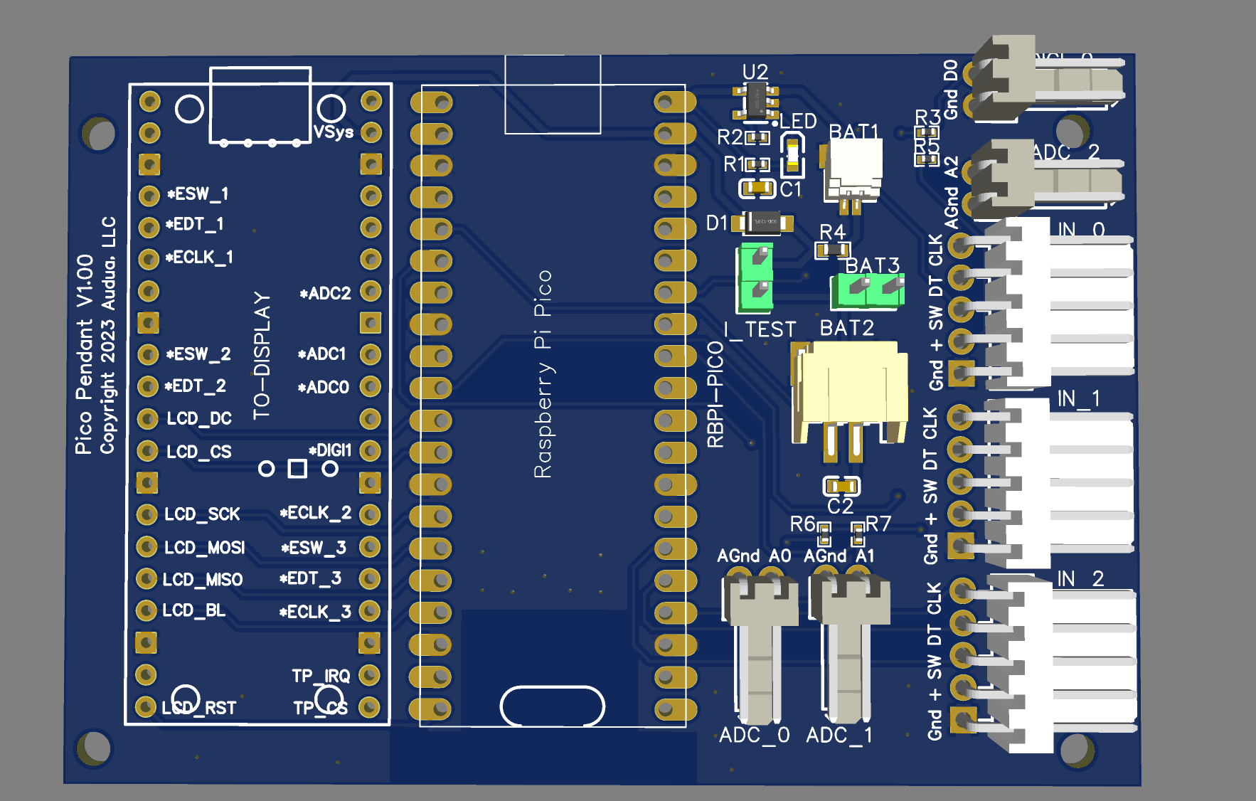
Here's a quick view of the board (V1.00).
The board is designed to fit onto this 3.5" touchscreen display -> https://www.waveshare.com/wiki/Pico-ResTouch-LCD-3.5 but it should work with most any display, just not as well-mounted. The carrier board holes fit the display.
The WaveShare display has a socket for a Raspberry Pi Pico. The carrier board has two Pico 'sockets'. The center socket is to flush-mount or pin-mount a Raspberry Pi Pico W, the other just has pins mounted for the display board.
There is a LiPo battery charger and voltage source circuit, as well as 7 input sockets: 1 digital input, 3 analog inputs (for potentiometers or ladder switches), and 3 multi-inputs for standard arduino rotary encoders or just usable as 3 digital i/o's per input. There are three different optional battery connectors in parallel - a 1mm JST, a 2mm JST, and a molex 2-pin. In addition there's a primitive current test pin.
The sample image of the pendant shows it with three rotary encoders - which I think will be my first attempt. By default they'll do X,Y,Z positioning.
I build these at JLCPCB in China, where the cost per board is tiny (<$5) but the setup+mail costs are close to $40/order. The first run was 5 boards which may be the last run if they work.
For software I'm planning to use MicroPython and have it talk to the Duet boards via the REST api. If this fails (so far it looks good) I'll switch to C++.
Mark
-
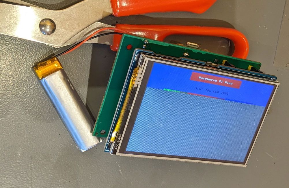
The first batch has shown up and I've adequately (good word) soldered the ic socket left. The center I've stuck a real plugin socket for testing (not shown). The mounting holes need to be moved left about 2.5mm but otherwise so far so good. I deliberately don't populate BAT2 or BAT3.
Strangely I've found out that my port-switchable USB hub apparently doesn't turn off the data lines since, with battery, this communicates with my PC USB even with the port off
 That's a useful feature for testing but still...
-
@markz nice! what will you use to build the UI on the pendant? Micropython directly?
-
@T3P3Tony At the moment I'm using the MicroPython Pico W daily build and it's working very reliably, though there's some strangeness with the dual core management. It currently is drawing that sample image and hosting web pages as a test of the wifi. The only concern I have is that it's approaching the 2MB flash limit with most of the core code done.
All of the ports are tested and working and I've ordered new boards that hopefully have the holes correctly seated although I don't really care that much since the enclosure can correct that so now I'm working on the software. This would take just a few days if I didn't have other things to do.
If you guys want a few of the boards I won't be using them all.
-
@markz thanks for the offer. Personally it would be wasted on me but possibly @Sindarius may have a use for one?
-
@markz i'd be interested in one
-
@markz this is awesome. I’d be interested in one.
-
@Sindarius @jay_s_uk If you could msg me mailing addresses I'll send them out. I have at least 3 spares. If you want the ones with the improved, maybe correct, mounting holes they rate to take about 3 weeks to get here.
-
Here's a pointer to a Youtube video showing a very very very early demo.
Update:: I connected the CNC (a 6XD) direct to ethernet instead of a wonky forwarder and slightly tweaked the code and it's looking way better for lag.

-
@markz Great video! Really love what you're doing with that setup.
-
Here's the first 'real' version in photos.
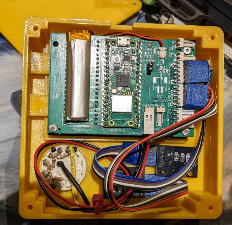
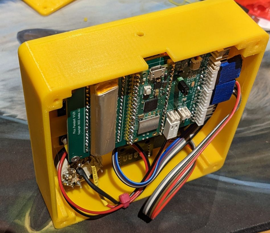
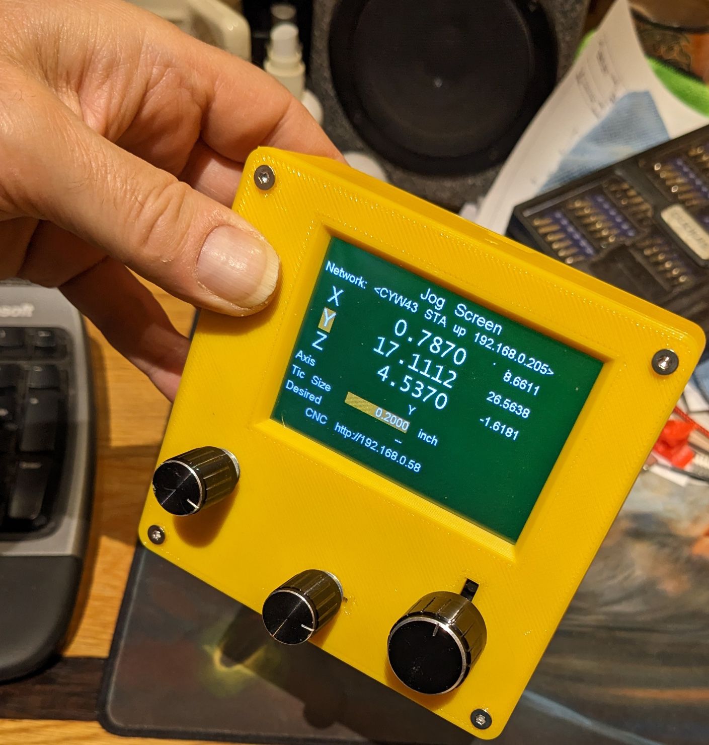
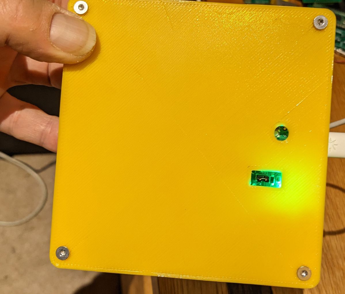
-
For anyone who's interested in building/using one of these, the documentation, source, schematics, ... is in On Github
The schematic+pcb+bom is designed for Jlcpcb using their EasyEda application so it's trivial (one click) to have one built.
The current state is: the unit works effectively, the Pico has a tiny Wifi antenna so a nearby router is a good thing, and MicroPython for the Pico W is still beta so the wifi code uses blocking I/O which can be a bit laggy.
I also haven't yet written the extra wifi support for Duet3d SBC since only my printer uses that.