Prints are being mirrored
-
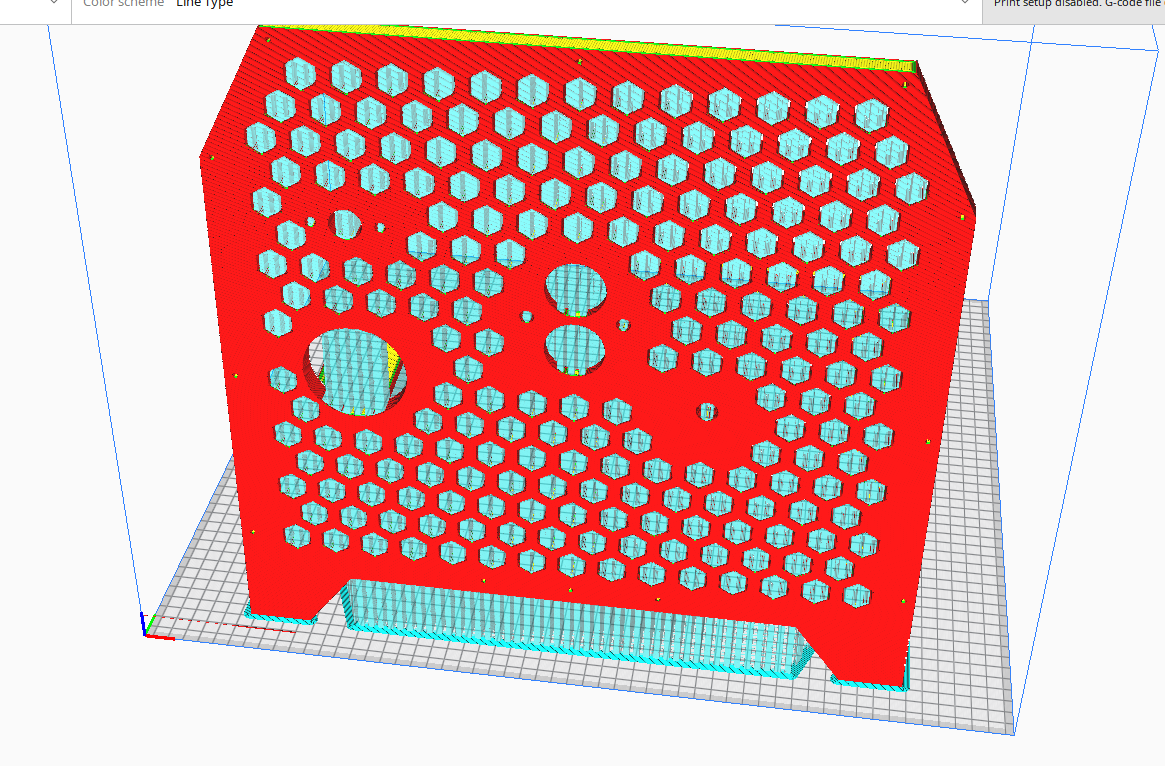
I have a duet mainboard 6HC wired to a coreXY printer. I am printing something that is asymmetrical and I realized my actual print is the mirror image of my gcode from cura. How could this be? Below is the image of what I see in Cura, but when this actually prints the large diameter hole is on the right (instead of the right) and so on. At first I thought I must be crazy but printed again and same thing.
-
@Feynman137 see the Important Note at the end of section https://docs.duet3d.com/en/User_manual/Machine_configuration/Configuration_coreXY#testing-motor-movement.
Duet WiFi hardware designer and firmware engineer
Please do not ask me for Duet support via PM or email, use the forum
http://www.escher3d.com, https://miscsolutions.wordpress.com -
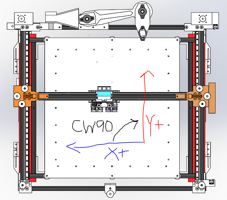
@dc42 thanks for the information, I put it in bold below. I believe I am configured to give mirror image prints unfortunately, could you confirm based on my schematic?
Important: make sure that you have chosen a right-hand axis system. That is, looking down on the printer the +Y direction should be 90 degrees anticlockwise from the +X direction. If instead it is 90 degrees clockwise, you have a left-hand axis system, which will give you mirror-image prints.
If this is true I will switch the side of my x-axis endstop and this should do the trick.
-
You don't need to move the endstop, you just need to change the configuration. Post your config.g and homing files and I can tell you specifically what needs to be changed, but in general, the endstop would need to be defined as low end, instead of high end, the x homing move direction would need to be negative, and the direction of rotation of the X axis would need to be verified.
The link DC42 shared has some tests you can perform to determine whether anything else needs to change to keep coreXY motion correct, such as swapping a motor connector or changing the direction of rotation.
-
Thank you so much. Right now both of my endstops are located at the bottom right of the overview I shared. They both are low end meaning they are the x and y 0 points. Let me know what you think I should change and I'll do this.
Config
; Configuration file for Duet 3 (firmware version 3)
; executed by the firmware on start-up
;
; generated by RepRapFirmware Configuration Tool v3.2.3 on Wed Jun 23 2021 23:47:21 GMT-0400 (Eastern Daylight Time)

; General preferences
G90                                             ; send absolute coordinates...
M83                                             ; ...but relative extruder moves
M550 P"Duet 3"                                  ; set printer name
M669 K1                                         ; select CoreXY mode

; Drives
M569 P0.0 S1                                    ; physical drive 0.0 goes forwards
M569 P0.1 S1                                    ; physical drive 0.1 goes forwards
M569 P0.2 S1									; physical drive 0.2 goes forwards
M569 P0.3 S1									; physical drive 0.3 goes forwards
M569 P0.4 S1									; physical drive 0.4 goes forwards
M569 P0.5 S1									; physical drive 0.5 goes forwards
M569 P1.1 S0                                    ; physical drive 1.1 goes backwards
M569 P1.2 S1                                    ; physical drive 1.2 goes forwards
M584 X0.0 Y0.1 Z0.2:0.3:0.4:0.5 E1.1:1.2        ; set drive mapping
M671 X674.55:674.55:-115.1:-115.1 Y-17.17:526.47:526.47:-17.17 S1 			; leadscrews at (xf,yi) (xf,yf) (xi,yf) (xi,yi)
M350 X16 Y16 Z16 E16:16 I1                      ; configure microstepping with interpolation
M92 X40.00 Y40.00 Z1200.00 E837:837        ; set steps per mm
M566 X900.00 Y900.00 Z150.00 E120.00:120.00      ; set maximum instantaneous speed changes (mm/min)
M203 X6000.00 Y6000.00 Z300.00 E1200.00:1200.00 ; set maximum speeds (mm/min)
M201 X500.00 Y500.00 Z10.00 E250.00:250.00      ; set accelerations (mm/s^2)
M906 X2100 Y2100 Z2800 E800:800 I50             ; set motor currents (mA) and motor idle factor in per cent
M84 S30                                         ; Set idle timeout

; Axis Limits
M208 X0 Y0 Z-2 S1                              ; set axis minima
M208 X550 Y500 Z451 S0                          ; set axis maxima

; Endstops
M574 X1 S1 P"!io4.in"                           ; configure active-low endstop for low end on X via pin !io1.in
M574 Y1 S1 P"!io2.in"                           ; configure active-low endstop for low end on Y via pin !io5.in
M574 Z2 S1 P"!io3.in"                           ; configure active-low endstop for low end on Z via pin !io3.in

; Z-Probe
M950 S0 C"io7.out"                              ; create servo pin 0 for BLTouch
M558 P9 C"^io7.in" H2 F100:50 T3000                ; set Z probe type to bltouch and the dive height + speeds
G31 X-23.9 Y33.2 Z4.5
;G31 X-23.9 Y28.2 Z4.5                          ; set Z probe trigger value, offset and trigger height
M557 X50:550 Y50:450 S50:100                        ; define mesh grid

; Heaters
M308 S0 P"1.temp0" Y"thermistor" T100000 B4138  ; configure sensor 0 as thermistor on expansion board pin 1.temp0
M950 H0 C"1.out0" T0                            ; create nozzle heater output on 1.out0 and map it to sensor 0
M307 H0 R1.567 K0.235:0.000 D5.97 E1.35 S1.00 B0 V24.0; disable bang-bang mode for heater  and set PWM limit
M143 H0 S280                                    ; set temperature limit for heater 0 to 280C

M308 S1 P"1.temp1" Y"thermistor" T100000 B4138  ; configure sensor 2 as thermistor on expansion board pin 1.temp1
M950 H1 C"1.out1" T1                            ; create nozzle heater output on 1.out2 and map it to sensor 1
M307 H1 B0 S1.00                                ; disable bang-bang mode for heater  and set PWM limit
M143 H1 S280                                    ; set temperature limit for heater 1 to 280C

; bed heater0
M308 S2 P"0.temp0" Y"thermistor" T100000 B4138    ; configure sensor 2 as thermistor on mainboard pin temp0
M950 H2 C"0.out9" T2                            ; create bed heater output on 1.out0 and map it to sensor 2
M140 P0 H2                                         ;assign H2 to bed heater0
M307 H2 B0 S10.00                                ; disable bang-bang mode for the bed heater and set PWM limit
M143 H2 S120                                     ;set temperature limit for heater 0 to 120C

; bed heater1
M308 S3 P"0.temp1" Y"thermistor" T100000 B4138    ; configure sensor 3 as thermistor on mainboard pin temp1
M950 H3 C"0.out6" T3                             ; create bed heater output on 1.out0 and map it to sensor 3
M140 P1 H3                                         ;assign H2 to bed heater0
M307 H3 B0 S10.00                                ; disable bang-bang mode for the bed heater and set PWM limit
M143 H3 S120                                     ;set temperature limit for heater 0 to 120C

; bed heater2
M308 S4 P"0.temp2" Y"thermistor" T100000 B4138    ; configure sensor 4 as thermistor on mainboard pin temp2
M950 H4 C"0.out5" T4                             ; create bed heater output on 1.out0 and map it to sensor 4
M140 P2 H4                                          ;assign H2 to bed heater0
M307 H4 B0 S10.00                                ; disable bang-bang mode for the bed heater and set PWM limit
M143 H4 S120                                     ;set temperature limit for heater 0 to 120C

; bed heater3
M308 S5 P"0.temp3" Y"thermistor" T100000 B4138    ; configure sensor 5 as thermistor on mainboard pin temp3
M950 H5 C"0.out4" T5                             ; create bed heater output on 1.out0 and map it to sensor 5
M140 P3 H5                                      ;assign H2 to bed heater0
M307 H5 B0 S10.00                                ; disable bang-bang mode for the bed heater and set PWM limit
M143 H5 S120                                     ;set temperature limit for heater 0 to 120C


; Fans
M950 F0 C"1.out7" Q500                          ; create fan 0 on pin 1.out7 and set its frequency
M106 P0 S255 H-1                                  ; set fan 0 value. Thermostatic control is turned off
M950 F1 C"1.out8" Q500                          ; create fan 1 on pin 1.out8 and set its frequency
M106 P1 S0 H-1                                  ; set fan 1 value. Thermostatic control is turned off
M950 F2 C"0.out7" Q500                          ; create fan 2 on pin 1.out7 and set its frequency
M106 P2 S255 H-1                                  ; set fan 0 value. Thermostatic control is turned off
M950 F3 C"0.out8" Q500                          ; create fan 3 on pin 1.out8 and set its frequency
M106 P3 S255 H-1                                  ; set fan 1 value. Thermostatic control is turned off

; Tools
M563 P0 S"left extruder" D0 H0 F0               ; define tool 0
G10 P0 X0 Y0 Z0                         ; set tool 0 axis offsets
G10 P0 R0 S0                                    ; set initial tool 0 active and standby temperatures to 0C
;M563 P1 S"right extruder" D1 H1 F1                define tool 1
;G10 P1 X-47.8 Y0 Z0                        ; set tool 1 axis offsets
G10 P0 R0 S0                                    ; set initial tool 0 active and standby temperatures to 0C

; Custom settings are not defined

; Miscellaneous
M575 P1 S1 B57600                               ; enable support for PanelDue
Homing
; homeall.g ; called to home all axes ; ; generated by RepRapFirmware Configuration Tool v3.2.3 on Wed Jun 23 2021 23:47:22 GMT-0400 (Eastern Daylight Time) G91 ; relative positioning G1 H2 Z7 F300 ; lower Z relative to current position G1 H1 X-640 Y-545 F1800 ; move quickly to X or Y endstop and stop there (first pass) G1 H1 X-640 ; home X axis G1 H1 Y-545 ; home Y axis G1 X5 Y5 F6000 ; go back a few mm G1 H1 X-640 F1000 ; move slowly to X axis endstop once more (second pass) G1 H1 Y-545 ; then move slowly to Y axis endstop G1 X5 ;move x axis G92 X0 ;compensate to keep BL touch on plate G1 Y35 ;move y from unprintable region G92 Y0 ;compensate to keep BL touch on plate G1 X275 F1800 ;move x to center of build plate G1 Y250 F1800 ;move y to center of build plate M558 F100 ;adjust zprobing speed G30 G1 Z5 F100 ;move build plate down slowly for second pass M558 F10 ;adjust zprobing speed to slow G30 G1 H2 Z10 F300 ; lower Z relative to current position -
; Endstops
M574 X1 S1 P"!io4.in"
This would become X2 instead of X1 to make it a high end endstop since the X endstop is on the right side and we want +x moves to go right.
; Endstops
M574 X2 S1 P"!io4.in"
In your homing files, any X - moves would need to become X + moves.
After making those changes you would need to perform the motor test from the corexy commissioning link to ensure things are going to right direction and make any needed changes.
Also note that you will likely need to adjust the sign of any X axis offsets you have, like G31 now that -X is to the left, and +X is to the right. Same for extruder offset, etc.
-
@Phaedrux Thank you I believe this did the trick!
-
 undefined Phaedrux marked this topic as a question
-
undefined Phaedrux has marked this topic as solved