It appears the issue was incompatible firmware between the expansion board and my mainboard but I issued the M997 command and now I can turn on the heater.
Best posts made by Feynman137
-
RE: Cannot get extruder heater to turn onposted in Using Duet Controllers
-
RE: Firmware for 4 Zone Bed Heaterposted in Firmware installation
@phaedrux @fcwilt Thanks for the M140 P comment I have added this to the code, and made the other described changes it should be up to date.
; Configuration file for Duet 3 (firmware version 3) ; executed by the firmware on start-up ; ; generated by RepRapFirmware Configuration Tool v3.2.3 on Wed Jun 23 2021 23:47:21 GMT-0400 (Eastern Daylight Time) ; General preferences G90 ; send absolute coordinates... M83 ; ...but relative extruder moves M550 P"Duet 3" ; set printer name M669 K1 ; select CoreXY mode ; Drives M569 P0.0 S1 ; physical drive 0.0 goes forwards M569 P0.1 S1 ; physical drive 0.1 goes forwards M569 P0.2 S1 ; physical drive 0.2 goes forwards M569 P0.3 S1 ; physical drive 0.3 goes forwards M569 P0.4 S1 ; physical drive 0.4 goes forwards M569 P0.5 S1 ; physical drive 0.5 goes forwards M569 P1.1 S1 ; physical drive 1.1 goes forwards M569 P1.2 S1 ; physical drive 1.2 goes forwards M584 X0.0 Y0.1 Z0.2:0.3:0.4:0.5 E1.1:1.2 ; set drive mapping M350 X16 Y16 Z16 E16:16 I1 ; configure microstepping with interpolation M92 X40.00 Y40.00 Z400.00 E420.00:420.00 ; set steps per mm M566 X900.00 Y900.00 Z60.00 E120.00:120.00 ; set maximum instantaneous speed changes (mm/min) M203 X6000.00 Y6000.00 Z120.00 E1200.00:1200.00 ; set maximum speeds (mm/min) M201 X500.00 Y500.00 Z10.00 E250.00:250.00 ; set accelerations (mm/s^2) M906 X1500 Y1500 Z1500 E800:800 I30 ; set motor currents (mA) and motor idle factor in per cent M84 S30 ; Set idle timeout ; Axis Limits M208 X0 Y0 Z0 S1 ; set axis minima M208 X600 Y540 Z496 S0 ; set axis maxima ; Endstops M574 X1 S1 P"!io4.in" ; configure active-low endstop for low end on X via pin !io1.in M574 Y1 S1 P"!io5.in" ; configure active-low endstop for low end on Y via pin !io5.in M574 Z2 S1 P"!io3.in" ; configure active-low endstop for low end on Z via pin !io3.in ; Z-Probe M950 S0 C"io7.out" ; create servo pin 0 for BLTouch M558 P9 C"^io7.in" H7 F120 T6000 ; set Z probe type to bltouch and the dive height + speeds G31 P500 X0 Y0 Z1.67 ; set Z probe trigger value, offset and trigger height M557 X10:600 Y10:540 S100 ; define mesh grid ; Heaters M308 S0 P"1.temp0" Y"thermistor" T100000 B4138 ; configure sensor 0 as thermistor on expansion board pin 1.temp0 M950 H0 C"1.out0" T0 ; create nozzle heater output on 1.out0 and map it to sensor 0 M307 H0 B0 S1.00 ; disable bang-bang mode for heater and set PWM limit M143 H0 S280 ; set temperature limit for heater 0 to 280C M308 S1 P"1.temp1" Y"thermistor" T100000 B4138 ; configure sensor 2 as thermistor on expansion board pin 1.temp1 M950 H1 C"1.out1" T1 ; create nozzle heater output on 1.out2 and map it to sensor 1 M307 H1 B0 S1.00 ; disable bang-bang mode for heater and set PWM limit M143 H1 S280 ; set temperature limit for heater 1 to 280C ; bed heater0 M308 S2 P"0.temp0" Y"thermistor" T100000 B4138 ; configure sensor 2 as thermistor on mainboard pin temp0 M950 H2 C"0.out9" T2 ; create bed heater output on 1.out0 and map it to sensor 2 M140 P0 H2 ;assign H2 to bed heater0 M307 H2 B0 S10.00 ; disable bang-bang mode for the bed heater and set PWM limit M143 H2 S120 ;set temperature limit for heater 0 to 120C ; bed heater1 M308 S3 P"0.temp1" Y"thermistor" T100000 B4138 ; configure sensor 3 as thermistor on mainboard pin temp1 M950 H3 C"0.out6" T3 ; create bed heater output on 1.out0 and map it to sensor 3 M140 P1 H3 ;assign H2 to bed heater0 M307 H3 B0 S10.00 ; disable bang-bang mode for the bed heater and set PWM limit M143 H3 S120 ;set temperature limit for heater 0 to 120C ; bed heater2 M308 S4 P"0.temp2" Y"thermistor" T100000 B4138 ; configure sensor 4 as thermistor on mainboard pin temp2 M950 H4 C"0.out5" T4 ; create bed heater output on 1.out0 and map it to sensor 4 M140 P2 H4 ;assign H2 to bed heater0 M307 H4 B0 S10.00 ; disable bang-bang mode for the bed heater and set PWM limit M143 H4 S120 ;set temperature limit for heater 0 to 120C ; bed heater3 M308 S5 P"0.temp3" Y"thermistor" T100000 B4138 ; configure sensor 5 as thermistor on mainboard pin temp3 M950 H5 C"0.out4" T5 ; create bed heater output on 1.out0 and map it to sensor 5 M140 P3 H5 ;assign H2 to bed heater0 M307 H5 B0 S10.00 ; disable bang-bang mode for the bed heater and set PWM limit M143 H5 S120 ;set temperature limit for heater 0 to 120C ; Fans M950 F0 C"1.out7" Q500 ; create fan 0 on pin 1.out7 and set its frequency M106 P0 S0 H-1 ; set fan 0 value. Thermostatic control is turned off M950 F1 C"1.out8" Q500 ; create fan 1 on pin 1.out8 and set its frequency M106 P1 S1 H-1 ; set fan 1 value. Thermostatic control is turned off ; Tools M563 P0 D0 H0 F0 ; define tool 0 G10 P0 X23.9 Y-28.21 Z0 ; set tool 0 axis offsets G10 P0 R0 S0 ; set initial tool 0 active and standby temperatures to 0C M563 P1 D1 H1 F1 ; define tool 1 G10 P1 X-23.9 Y-28.21 Z0 ; set tool 1 axis offsets G10 P1 R0 S0 ; set initial tool 0 active and standby temperatures to 0C ; Custom settings are not defined ; Miscellaneous M575 P1 S1 B57600 ; enable support for PanelDue -
RE: Prints are being mirroredposted in General Discussion
@Phaedrux Thank you I believe this did the trick!
-
RE: Gcode command for single stepper on z axisposted in Gcode meta commands
@fcwilt
Yea each stepper has its own driver all of the drivers are tied to the z axis in the config file.I think the auto bed leveling is exactly what I am looking for, but I just need to do some reading to understand how to do this with my set-up.
-
RE: Problems with Duet3 Expansion 3HC Connectingposted in Firmware installation
@dc42 The cable did the trick sir. Thank you for your advice!
-
RE: Firmware for hotend of dual extruder headposted in Firmware installation
@deckingman thank you very much for this info. Especially the M584 comment, I had this all messed up. And in my head I was wondering how the code was tying heater to its respective extrusion drive. So this comment answers this question for me, it is in the tool definition. @Phaedrux thank you for the guidance you were correct I had not added the expansion board in the config tool. After doing this I was able to see the format that you displayed in your answer. I am posting my updated config.g file below.
; Configuration file for Duet 3 (firmware version 3)
; executed by the firmware on start-up
;
; generated by RepRapFirmware Configuration Tool v3.2.3 on Wed Jun 23 2021 23:47:21 GMT-0400 (Eastern Daylight Time)

; General preferences
G90                                             ; send absolute coordinates...
M83                                             ; ...but relative extruder moves
M550 P"Duet 3"                                  ; set printer name
M669 K1                                         ; select CoreXY mode

; Drives
M569 P0.0 S1                                    ; physical drive 0.0 goes forwards
M569 P0.1 S1                                    ; physical drive 0.1 goes forwards
M569 P0.2 S1									; physical drive 0.2 goes forwards
M569 P0.3 S1									; physical drive 0.3 goes forwards
M569 P0.4 S1									; physical drive 0.4 goes forwards
M569 P0.5 S1									; physical drive 0.5 goes forwards
M569 P1.1 S1                                    ; physical drive 1.1 goes forwards
M569 P1.2 S1                                    ; physical drive 1.2 goes forwards
M584 X0.0 Y0.1 Z0.2:0.3:0.4:0.5 E1.1:1.2        ; set drive mapping
M350 X16 Y16 Z16 E16:16 I1                      ; configure microstepping with interpolation
M92 X40.00 Y40.00 Z400.00 E420.00:420.00        ; set steps per mm
M566 X900.00 Y900.00 Z60.00 E120.00:120.00      ; set maximum instantaneous speed changes (mm/min)
M203 X6000.00 Y6000.00 Z120.00 E1200.00:1200.00 ; set maximum speeds (mm/min)
M201 X500.00 Y500.00 Z10.00 E250.00:250.00      ; set accelerations (mm/s^2)
M906 X1500 Y1500 Z1500 E800:800 I30             ; set motor currents (mA) and motor idle factor in per cent
M84 S30                                         ; Set idle timeout

; Axis Limits
M208 X0 Y0 Z0 S1                              ; set axis minima
M208 X600 Y540 Z496 S0                          ; set axis maxima

; Endstops
M574 X1 S1 P"!io4.in"                           ; configure active-low endstop for low end on X via pin !io1.in
M574 Y1 S1 P"!io5.in"                           ; configure active-low endstop for low end on Y via pin !io5.in
M574 Z2 S1 P"!io3.in"                           ; configure active-low endstop for low end on Z via pin !io3.in

; Z-Probe
M950 S0 C"io7.out"                              ; create servo pin 0 for BLTouch
M558 P9 C"^io7.in" H7 F120 T6000                ; set Z probe type to bltouch and the dive height + speeds
G31 P500 X0 Y0 Z1.67                            ; set Z probe trigger value, offset and trigger height
M557 X10:600 Y10:540 S100                        ; define mesh grid

; Heaters

M308 S0 P"1.temp0" Y"thermistor" T100000 B4138  ; configure sensor 0 as thermistor on expansion board pin 1.temp0
M950 H0 C"1.out0" T0                            ; create nozzle heater output on 1.out0 and map it to sensor 0
M307 H0 B0 S1.00                                ; disable bang-bang mode for heater  and set PWM limit
M143 H0 S280                                    ; set temperature limit for heater 0 to 280C
M308 S1 P"1.temp1" Y"thermistor" T100000 B4138  ; configure sensor 2 as thermistor on expansion board pin 1.temp1
M950 H1 C"1.out1" T1                            ; create nozzle heater output on 1.out2 and map it to sensor 1
M307 H1 B0 S1.00                                ; disable bang-bang mode for heater  and set PWM limit
M143 H1 S280                                    ; set temperature limit for heater 1 to 280C

; bed heater0
M308 S2 P"0.temp0" Y"thermistor" T100000 B4138    ; configure sensor 2 as thermistor on mainboard pin temp0
M950 H2 C"0.out9" T2                            ; create bed heater output on 1.out0 and map it to sensor 2
M140 P0 H2                                         ;assign H2 to bed heater0
M307 H2 B0 S10.00                                ; disable bang-bang mode for the bed heater and set PWM limit
M143 H2 S120                                     ;set temperature limit for heater 0 to 120C

; bed heater1
M308 S3 P"0.temp1" Y"thermistor" T100000 B4138    ; configure sensor 3 as thermistor on mainboard pin temp1
M950 H3 C"0.out6" T3                             ; create bed heater output on 1.out0 and map it to sensor 3
M140 P1 H3                                         ;assign H2 to bed heater0
M307 H3 B0 S10.00                                ; disable bang-bang mode for the bed heater and set PWM limit
M143 H3 S120                                     ;set temperature limit for heater 0 to 120C

; bed heater2
M308 S4 P"0.temp2" Y"thermistor" T100000 B4138    ; configure sensor 4 as thermistor on mainboard pin temp2
M950 H4 C"0.out5" T4                             ; create bed heater output on 1.out0 and map it to sensor 4
M140 P2 H4                                          ;assign H2 to bed heater0
M307 H4 B0 S10.00                                ; disable bang-bang mode for the bed heater and set PWM limit
M143 H4 S120                                     ;set temperature limit for heater 0 to 120C

; bed heater3
M308 S5 P"0.temp3" Y"thermistor" T100000 B4138    ; configure sensor 5 as thermistor on mainboard pin temp3
M950 H5 C"0.out4" T5                             ; create bed heater output on 1.out0 and map it to sensor 5
M140 P3 H5                                      ;assign H2 to bed heater0
M307 H5 B0 S10.00                                ; disable bang-bang mode for the bed heater and set PWM limit
M143 H5 S120                                     ;set temperature limit for heater 0 to 120C


; Fans
M950 F0 C"1.out7" Q500                          ; create fan 0 on pin 1.out7 and set its frequency
M106 P0 S0 H-1                                  ; set fan 0 value. Thermostatic control is turned off
M950 F1 C"1.out8" Q500                          ; create fan 1 on pin 1.out8 and set its frequency
M106 P1 S1 H-1                                  ; set fan 1 value. Thermostatic control is turned off

; Tools
M563 P0 D0 H0 F0                                ; define tool 0
G10 P0 X23.9 Y-28.21 Z0                          ; set tool 0 axis offsets
G10 P0 R0 S0                                    ; set initial tool 0 active and standby temperatures to 0C
M563 P1 D1 H1 F1                                ; define tool 1
G10 P1 X-23.9 Y-28.21 Z0                         ; set tool 1 axis offsets
G10 P1 R0 S0                                    ; set initial tool 0 active and standby temperatures to 0C

; Custom settings are not defined

; Miscellaneous
M575 P1 S1 B57600                               ; enable support for PanelDue
Latest posts made by Feynman137
-
RE: Cannot get driver to install on Windows 10posted in General Discussion
@droftarts What com5?
Edit, the guides are actually the same so is the link. But your point of installing on the com device is what I needed. I was trying to install the driver on the other devices. I ran it on the com3 and everything installed fine! Thanks
-
Cannot get driver to install on Windows 10posted in General Discussion
I am trying to setup the Mini5+ but cannot seem to get the driver installed. I am following this guide there is a link to github for the driver. I download this link to file then I connect to my mini5+ with the red USB shipped to me from duet, right click and attempt to update the driver.
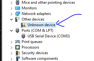
I get this message every time
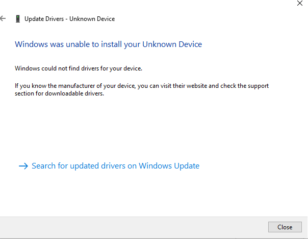
What could be wrong?
-
Local web address for 2nd duet mainboardposted in General Discussion
I just finished wiring up my 2nd duet mainboard. My existing printer is using the mainboard 6hc this one is just duet mini 5+
What will be the web address of my new printer. If the DWC is already duetlocal for the first one. Will I need to now use each printers IP address in the web browser now?
-
RE: Prints are being mirroredposted in General Discussion
@Phaedrux Thank you I believe this did the trick!
-
RE: Prints are being mirroredposted in General Discussion
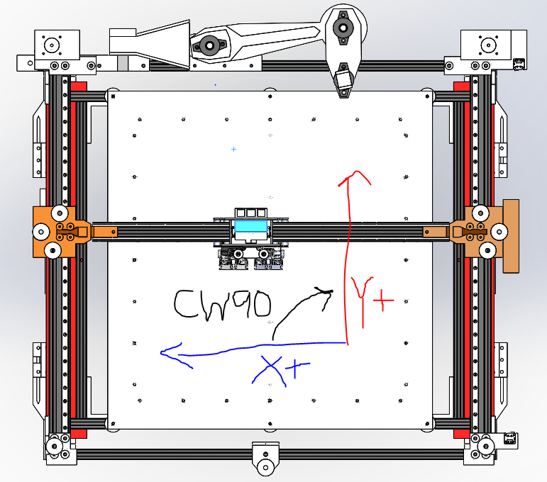
Thank you so much. Right now both of my endstops are located at the bottom right of the overview I shared. They both are low end meaning they are the x and y 0 points. Let me know what you think I should change and I'll do this.
Config
; Configuration file for Duet 3 (firmware version 3)
; executed by the firmware on start-up
;
; generated by RepRapFirmware Configuration Tool v3.2.3 on Wed Jun 23 2021 23:47:21 GMT-0400 (Eastern Daylight Time)

; General preferences
G90                                             ; send absolute coordinates...
M83                                             ; ...but relative extruder moves
M550 P"Duet 3"                                  ; set printer name
M669 K1                                         ; select CoreXY mode

; Drives
M569 P0.0 S1                                    ; physical drive 0.0 goes forwards
M569 P0.1 S1                                    ; physical drive 0.1 goes forwards
M569 P0.2 S1									; physical drive 0.2 goes forwards
M569 P0.3 S1									; physical drive 0.3 goes forwards
M569 P0.4 S1									; physical drive 0.4 goes forwards
M569 P0.5 S1									; physical drive 0.5 goes forwards
M569 P1.1 S0                                    ; physical drive 1.1 goes backwards
M569 P1.2 S1                                    ; physical drive 1.2 goes forwards
M584 X0.0 Y0.1 Z0.2:0.3:0.4:0.5 E1.1:1.2        ; set drive mapping
M671 X674.55:674.55:-115.1:-115.1 Y-17.17:526.47:526.47:-17.17 S1 			; leadscrews at (xf,yi) (xf,yf) (xi,yf) (xi,yi)
M350 X16 Y16 Z16 E16:16 I1                      ; configure microstepping with interpolation
M92 X40.00 Y40.00 Z1200.00 E837:837        ; set steps per mm
M566 X900.00 Y900.00 Z150.00 E120.00:120.00      ; set maximum instantaneous speed changes (mm/min)
M203 X6000.00 Y6000.00 Z300.00 E1200.00:1200.00 ; set maximum speeds (mm/min)
M201 X500.00 Y500.00 Z10.00 E250.00:250.00      ; set accelerations (mm/s^2)
M906 X2100 Y2100 Z2800 E800:800 I50             ; set motor currents (mA) and motor idle factor in per cent
M84 S30                                         ; Set idle timeout

; Axis Limits
M208 X0 Y0 Z-2 S1                              ; set axis minima
M208 X550 Y500 Z451 S0                          ; set axis maxima

; Endstops
M574 X1 S1 P"!io4.in"                           ; configure active-low endstop for low end on X via pin !io1.in
M574 Y1 S1 P"!io2.in"                           ; configure active-low endstop for low end on Y via pin !io5.in
M574 Z2 S1 P"!io3.in"                           ; configure active-low endstop for low end on Z via pin !io3.in

; Z-Probe
M950 S0 C"io7.out"                              ; create servo pin 0 for BLTouch
M558 P9 C"^io7.in" H2 F100:50 T3000                ; set Z probe type to bltouch and the dive height + speeds
G31 X-23.9 Y33.2 Z4.5
;G31 X-23.9 Y28.2 Z4.5                          ; set Z probe trigger value, offset and trigger height
M557 X50:550 Y50:450 S50:100                        ; define mesh grid

; Heaters
M308 S0 P"1.temp0" Y"thermistor" T100000 B4138  ; configure sensor 0 as thermistor on expansion board pin 1.temp0
M950 H0 C"1.out0" T0                            ; create nozzle heater output on 1.out0 and map it to sensor 0
M307 H0 R1.567 K0.235:0.000 D5.97 E1.35 S1.00 B0 V24.0; disable bang-bang mode for heater  and set PWM limit
M143 H0 S280                                    ; set temperature limit for heater 0 to 280C

M308 S1 P"1.temp1" Y"thermistor" T100000 B4138  ; configure sensor 2 as thermistor on expansion board pin 1.temp1
M950 H1 C"1.out1" T1                            ; create nozzle heater output on 1.out2 and map it to sensor 1
M307 H1 B0 S1.00                                ; disable bang-bang mode for heater  and set PWM limit
M143 H1 S280                                    ; set temperature limit for heater 1 to 280C

; bed heater0
M308 S2 P"0.temp0" Y"thermistor" T100000 B4138    ; configure sensor 2 as thermistor on mainboard pin temp0
M950 H2 C"0.out9" T2                            ; create bed heater output on 1.out0 and map it to sensor 2
M140 P0 H2                                         ;assign H2 to bed heater0
M307 H2 B0 S10.00                                ; disable bang-bang mode for the bed heater and set PWM limit
M143 H2 S120                                     ;set temperature limit for heater 0 to 120C

; bed heater1
M308 S3 P"0.temp1" Y"thermistor" T100000 B4138    ; configure sensor 3 as thermistor on mainboard pin temp1
M950 H3 C"0.out6" T3                             ; create bed heater output on 1.out0 and map it to sensor 3
M140 P1 H3                                         ;assign H2 to bed heater0
M307 H3 B0 S10.00                                ; disable bang-bang mode for the bed heater and set PWM limit
M143 H3 S120                                     ;set temperature limit for heater 0 to 120C

; bed heater2
M308 S4 P"0.temp2" Y"thermistor" T100000 B4138    ; configure sensor 4 as thermistor on mainboard pin temp2
M950 H4 C"0.out5" T4                             ; create bed heater output on 1.out0 and map it to sensor 4
M140 P2 H4                                          ;assign H2 to bed heater0
M307 H4 B0 S10.00                                ; disable bang-bang mode for the bed heater and set PWM limit
M143 H4 S120                                     ;set temperature limit for heater 0 to 120C

; bed heater3
M308 S5 P"0.temp3" Y"thermistor" T100000 B4138    ; configure sensor 5 as thermistor on mainboard pin temp3
M950 H5 C"0.out4" T5                             ; create bed heater output on 1.out0 and map it to sensor 5
M140 P3 H5                                      ;assign H2 to bed heater0
M307 H5 B0 S10.00                                ; disable bang-bang mode for the bed heater and set PWM limit
M143 H5 S120                                     ;set temperature limit for heater 0 to 120C


; Fans
M950 F0 C"1.out7" Q500                          ; create fan 0 on pin 1.out7 and set its frequency
M106 P0 S255 H-1                                  ; set fan 0 value. Thermostatic control is turned off
M950 F1 C"1.out8" Q500                          ; create fan 1 on pin 1.out8 and set its frequency
M106 P1 S0 H-1                                  ; set fan 1 value. Thermostatic control is turned off
M950 F2 C"0.out7" Q500                          ; create fan 2 on pin 1.out7 and set its frequency
M106 P2 S255 H-1                                  ; set fan 0 value. Thermostatic control is turned off
M950 F3 C"0.out8" Q500                          ; create fan 3 on pin 1.out8 and set its frequency
M106 P3 S255 H-1                                  ; set fan 1 value. Thermostatic control is turned off

; Tools
M563 P0 S"left extruder" D0 H0 F0               ; define tool 0
G10 P0 X0 Y0 Z0                         ; set tool 0 axis offsets
G10 P0 R0 S0                                    ; set initial tool 0 active and standby temperatures to 0C
;M563 P1 S"right extruder" D1 H1 F1                define tool 1
;G10 P1 X-47.8 Y0 Z0                        ; set tool 1 axis offsets
G10 P0 R0 S0                                    ; set initial tool 0 active and standby temperatures to 0C

; Custom settings are not defined

; Miscellaneous
M575 P1 S1 B57600                               ; enable support for PanelDue
Homing
; homeall.g ; called to home all axes ; ; generated by RepRapFirmware Configuration Tool v3.2.3 on Wed Jun 23 2021 23:47:22 GMT-0400 (Eastern Daylight Time) G91 ; relative positioning G1 H2 Z7 F300 ; lower Z relative to current position G1 H1 X-640 Y-545 F1800 ; move quickly to X or Y endstop and stop there (first pass) G1 H1 X-640 ; home X axis G1 H1 Y-545 ; home Y axis G1 X5 Y5 F6000 ; go back a few mm G1 H1 X-640 F1000 ; move slowly to X axis endstop once more (second pass) G1 H1 Y-545 ; then move slowly to Y axis endstop G1 X5 ;move x axis G92 X0 ;compensate to keep BL touch on plate G1 Y35 ;move y from unprintable region G92 Y0 ;compensate to keep BL touch on plate G1 X275 F1800 ;move x to center of build plate G1 Y250 F1800 ;move y to center of build plate M558 F100 ;adjust zprobing speed G30 G1 Z5 F100 ;move build plate down slowly for second pass M558 F10 ;adjust zprobing speed to slow G30 G1 H2 Z10 F300 ; lower Z relative to current position -
RE: Prints are being mirroredposted in General Discussion
@dc42 thanks for the information, I put it in bold below. I believe I am configured to give mirror image prints unfortunately, could you confirm based on my schematic?
Important: make sure that you have chosen a right-hand axis system. That is, looking down on the printer the +Y direction should be 90 degrees anticlockwise from the +X direction. If instead it is 90 degrees clockwise, you have a left-hand axis system, which will give you mirror-image prints.
If this is true I will switch the side of my x-axis endstop and this should do the trick.
-
Prints are being mirroredposted in General Discussion
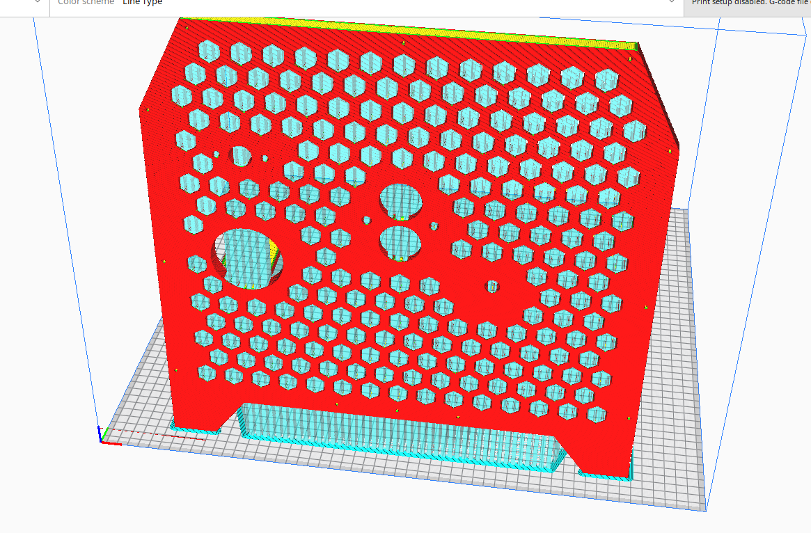
I have a duet mainboard 6HC wired to a coreXY printer. I am printing something that is asymmetrical and I realized my actual print is the mirror image of my gcode from cura. How could this be? Below is the image of what I see in Cura, but when this actually prints the large diameter hole is on the right (instead of the right) and so on. At first I thought I must be crazy but printed again and same thing.
-
RE: When I pause during a print, printer does not home correctlyposted in General Discussion
@OwenD This is quite an interesting idea
-
RE: When I pause during a print, printer does not home correctlyposted in General Discussion
@OwenD I see now that it is not actually homing like you said but attempting to move to X0 Y0
@jens55 I did not mention the details of the printer like max sizes etc because the config.g for the printer is posted above. But the printer looks like this:
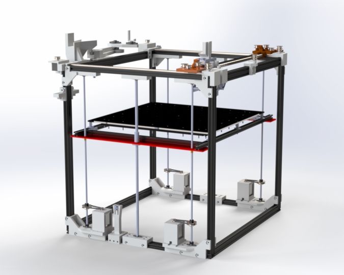
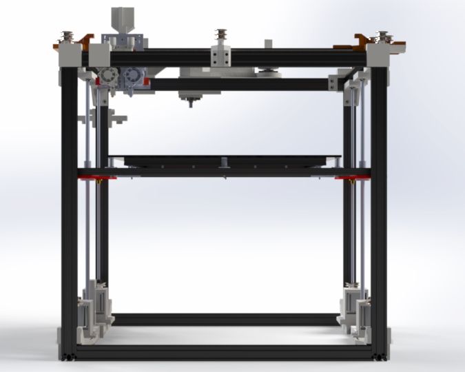

@Phaedrux you are correct the homing file is hitting the limit switch then moving away from it just slightly. There is an unprintable region due to the dual nozzles and bed clips etc.
The X0 and Y0 should be a safe place after the homing has been completed.
Slicer start gcode:
M106 S127 ;turn on extruder fan
M140 P0 S{material_bed_temperature} ;heated beds
M140 P1 S{material_bed_temperature}
M140 P2 S{material_bed_temperature}
M140 P3 S{material_bed_temperature}
G28 ; home G30 P0 X529.725 Y29.65 Z-99999 ; probe near a leadscrew G30 P1 X529.725 Y479.65 Z-99999 ; probe near a leadscrew G30 P2 X29.725 Y479.65 Z-99999 ; probe near a leadscrew G30 P3 X29.725 Y29.65 Z-99999 S4 ; probe near a leadscrew and calibrate 4 motors ; bed.g ; called to perform automatic bed compensation via G32 ; ; generated by RepRapFirmware Configuration Tool v3.2.3 on Wed Jun 23 2021 23:47:21 GMT-0400 (Eastern Daylight Time) M561 ; clear any bed transform G29 ; probe the bed and enable compensationThe M122 response is below. I was afraid to run the other command because I am in the middle of printing
M122
=== Diagnostics ===
RepRapFirmware for Duet 3 MB6HC version 3.4.2 (2022-09-13 15:17:43) running on Duet 3 MB6HC v1.01 (SBC mode)
Board ID: 08DJM-956BA-NA3TN-6J1FJ-3SN6K-198AU
Used output buffers: 1 of 40 (14 max)
=== RTOS ===
Static ram: 152664
Dynamic ram: 67408 of which 0 recycled
Never used RAM 127456, free system stack 112 words
Tasks: SBC(ready,99.8%,438) HEAT(notifyWait,2.8%,322) Move(notifyWait,56.2%,238) CanReceiv(notifyWait,3.3%,772) CanSender(notifyWait,0.2%,328) CanClock(delaying,0.8%,339) TMC(notifyWait,174.9%,57) MAIN(running,180.3%,923) IDLE(ready,0.3%,30), total 518.6%
Owned mutexes: HTTP(MAIN)
=== Platform ===
Last reset 107:20:19 ago, cause: power up
Last software reset at 2022-12-31 12:45, reason: User, Platform spinning, available RAM 130672, slot 0
Software reset code 0x0000 HFSR 0x00000000 CFSR 0x00000000 ICSR 0x00400000 BFAR 0x00000000 SP 0x00000000 Task SBC Freestk 0 n/a
Error status: 0x00
Aux0 errors 0,0,0
Step timer max interval 136
MCU temperature: min 11.4, current 18.7, max 21.7
Supply voltage: min 23.8, current 24.0, max 24.1, under voltage events: 0, over voltage events: 0, power good: yes
12V rail voltage: min 12.1, current 12.2, max 12.2, under voltage events: 0
Heap OK, handles allocated/used 99/0, heap memory allocated/used/recyclable 2048/12/12, gc cycles 0
Events: 0 queued, 0 completed
Driver 0: standstill, SG min 0, mspos 648, reads 25674, writes 41 timeouts 0
Driver 1: standstill, SG min 0, mspos 744, reads 25674, writes 41 timeouts 0
Driver 2: standstill, SG min 0, mspos 712, reads 25666, writes 49 timeouts 0
Driver 3: standstill, SG min 0, mspos 760, reads 25666, writes 49 timeouts 0
Driver 4: standstill, SG min 0, mspos 8, reads 25666, writes 49 timeouts 0
Driver 5: standstill, SG min 0, mspos 872, reads 25666, writes 49 timeouts 0
Date/time: 2023-01-05 00:06:25
Slowest loop: 65.97ms; fastest: 0.03ms
=== Storage ===
Free file entries: 10
SD card 0 not detected, interface speed: 37.5MBytes/sec
SD card longest read time 0.0ms, write time 0.0ms, max retries 0
=== Move ===
DMs created 125, segments created 12, maxWait 72177277ms, bed compensation in use: mesh, comp offset -0.396
=== MainDDARing ===
Scheduled moves 4379, completed 4379, hiccups 0, stepErrors 0, LaErrors 0, Underruns [0, 0, 42], CDDA state -1
=== AuxDDARing ===
Scheduled moves 0, completed 0, hiccups 0, stepErrors 0, LaErrors 0, Underruns [0, 0, 0], CDDA state -1
=== Heat ===
Bed heaters 2 3 4 5 -1 -1 -1 -1 -1 -1 -1 -1, chamber heaters -1 -1 -1 -1, ordering errs 0
Heater 0 is on, I-accum = 0.0
Heater 2 is on, I-accum = 0.0
Heater 3 is on, I-accum = 0.0
Heater 4 is on, I-accum = 0.0
Heater 5 is on, I-accum = 0.0
=== GCodes ===
Segments left: 0
Movement lock held by null
HTTP* is doing "M122" in state(s) 0
Telnet is idle in state(s) 0
File* is idle in state(s) 0
USB is idle in state(s) 0
Aux is idle in state(s) 0
Trigger* is idle in state(s) 0
Queue* is idle in state(s) 0
LCD is idle in state(s) 0
SBC is idle in state(s) 0
Daemon is idle in state(s) 0
Aux2 is idle in state(s) 0
Autopause is idle in state(s) 0
Code queue is empty
=== CAN ===
Messages queued 3764111, received 7728772, lost 0, boc 0
Longest wait 1ms for reply type 6042, peak Tx sync delay 395, free buffers 50 (min 46), ts 1932100/1932099/0
Tx timeouts 0,0,0,0,0,0
=== SBC interface ===
Transfer state: 5, failed transfers: 0, checksum errors: 0
RX/TX seq numbers: 21157/20032
SPI underruns 0, overruns 0
State: 5, disconnects: 0, timeouts: 0 total, 0 by SBC, IAP RAM available 0x2b1c8
Buffer RX/TX: 0/0-0, open files: 0
=== Duet Control Server ===
Duet Control Server v3.4.2
File /opt/dsf/sd/gcodes/CFFFP_base3ii.gcode is selected, paused
Code buffer space: 4096
Configured SPI speed: 8000000Hz, TfrRdy pin glitches: 1
Full transfers per second: 38.72, max time between full transfers: 88.0ms, max pin wait times: 3758.8ms/9.1ms
Codes per second: 0.81
Maximum length of RX/TX data transfers: 3480/1636