External Driver alarm wiring on 6XD
-
Hello there,
I have seen this question in the forums for other boards, but not the Duet 3 6xd with external drivers. This feels like one of those easy electronics questions that baffles people like me.
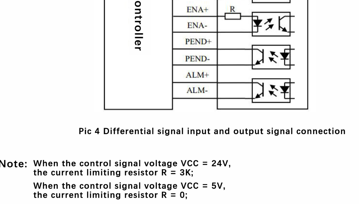
I have a Duet 3 6XD (on 3.4.5) running closed loop drivers (Lichuan LCDA257S) which is similar to a CL57T from stepperonline which has ALM+ and ALM-. I am confused on how to wire this up to the duet.
Duet 3 has a gnd pin and an Error pin (Dx_ERR) for each driver. The error pin meters 4.8v or so. I will check again tonight but I swear the pin is 4.8v regardless of the pull up/pull down selector.
If it is grounded or goes to 5V, it triggers the driver error. Not sure why it is both. The error pin also has a physical selector for pull up/pull down on the board. I tried wiring up to ALM+ and ALM- in just about every configuration I could try and it would never trigger the error. Nothing worked. I tried 5V to ALM+ and ALM- to dx_ERR pin, dx_ERR to ALM+ and ALM- to gnd, etc. I thought this was a simple optocoupler that would close the contact. In normal state the ALM+ and ALM- reads 16 mOhms, in alarm state, this goes to 0. Why can't I trigger the error on the duet??
Currently, my workaround is 24V to ALM+, ALM- to a separate 4 channel relay which closes a contact to ground out the dx_ERR pin. This works fine. I am ok with this workaround but it adds complexity.
Am I missing a resistor somewhere to be able to hook straight up to the duet? Perhaps the separate channel relay is safer anyway by putting an optocoupler in the way.
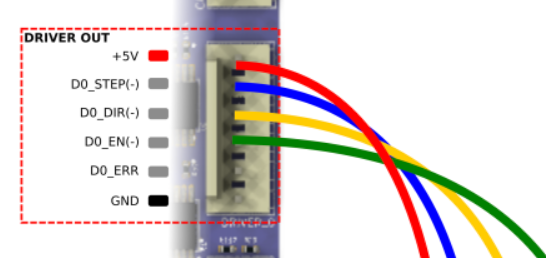
For clarity, this is the drive pins:
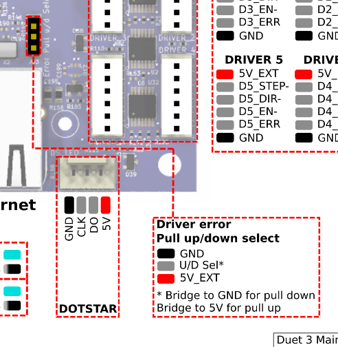
The duet
And the selector
-
@SDJ said in External Driver alarm wiring on 6XD:
Am I missing a resistor somewhere to be able to hook straight up to the duet? Perhaps the separate channel relay is safer anyway by putting an optocoupler in the way.
Since this setup will be using 5V signalling levels you do not need the resistor.
Currently, my workaround is 24V to ALM+, ALM- to a separate 4 channel relay which closes a contact to ground out the dx_ERR pin. This works fine.
we want to adapt this concept, but without the 24V and the relay
I know you may have tried this, but please try again.
- Wire 5V+ to ALM+ (presumably the same as you have wired it to the ENA+, DIR+, STEP+)
- Wire ALM- to Dn_ERR.
- Set the jumper to the "Pull-down" position.
With the ALM not triggered , Dn_ERR should read ~5V, with it triggered it should read ~0V
Edited: the jumper should be in the pull down position.
-
@T3P3Tony said in External Driver alarm wiring on 6XD:
I know you may have tried this, but please try again.
Wire 5V+ to ALM+ (presumably the same as you have wired it to the ENA+, DIR+, STEP+)
Wire ALM- to Dn_ERR.
Set the jumper to the "Pull-Up" position.With the ALM not triggered , Dn_ERR should read ~5V, with it triggered it should read ~0V
Don't you mean set the jumper to the pulldown position? i.e. bridge U/D to GND.
The alternative connection mechanism is:
- ALM+ to Dn_ERR
- ALM- to GND
- Bridge U/D Sel and +5V
Duet WiFi hardware designer and firmware engineer
Please do not ask me for Duet support via PM or email, use the forum
http://www.escher3d.com, https://miscsolutions.wordpress.com -
What is the best way to connect ALM+, ALM- and PEND+, PEND- from the HSS86 or CL-HSS86 Closed Loop Driver for Nema 34 to Duet 3 6XD main board ? I am currently building a Pnp Machine.
ALARM:
ALM+ = Alarm output +
ALM- = Alarm output -Option 1:
-
Wire 5V -----> ALM+ (The same as its wired to the ENA+, DIR+, STEP+)
-
Dx_ERR ------> ALM -
-
Bridge U/D Sel and GND (Pull Down)
Option 2:
-
Dx_ERR ------> ALM+
-
GND ------> ALM -
-
Bridge U/D Sel and +5V ( Pull Up )
Which of the above Alarm connection is recommended ?
PEND
PEND+ = In position signal output +
PEND- = In position signal output -How do you connect In-Position Signal to Duet 3 6XD correctly ?
Urgent help please if anyone can give some direction on this
-