Setting Up Input Shaping On Custom Printer
-
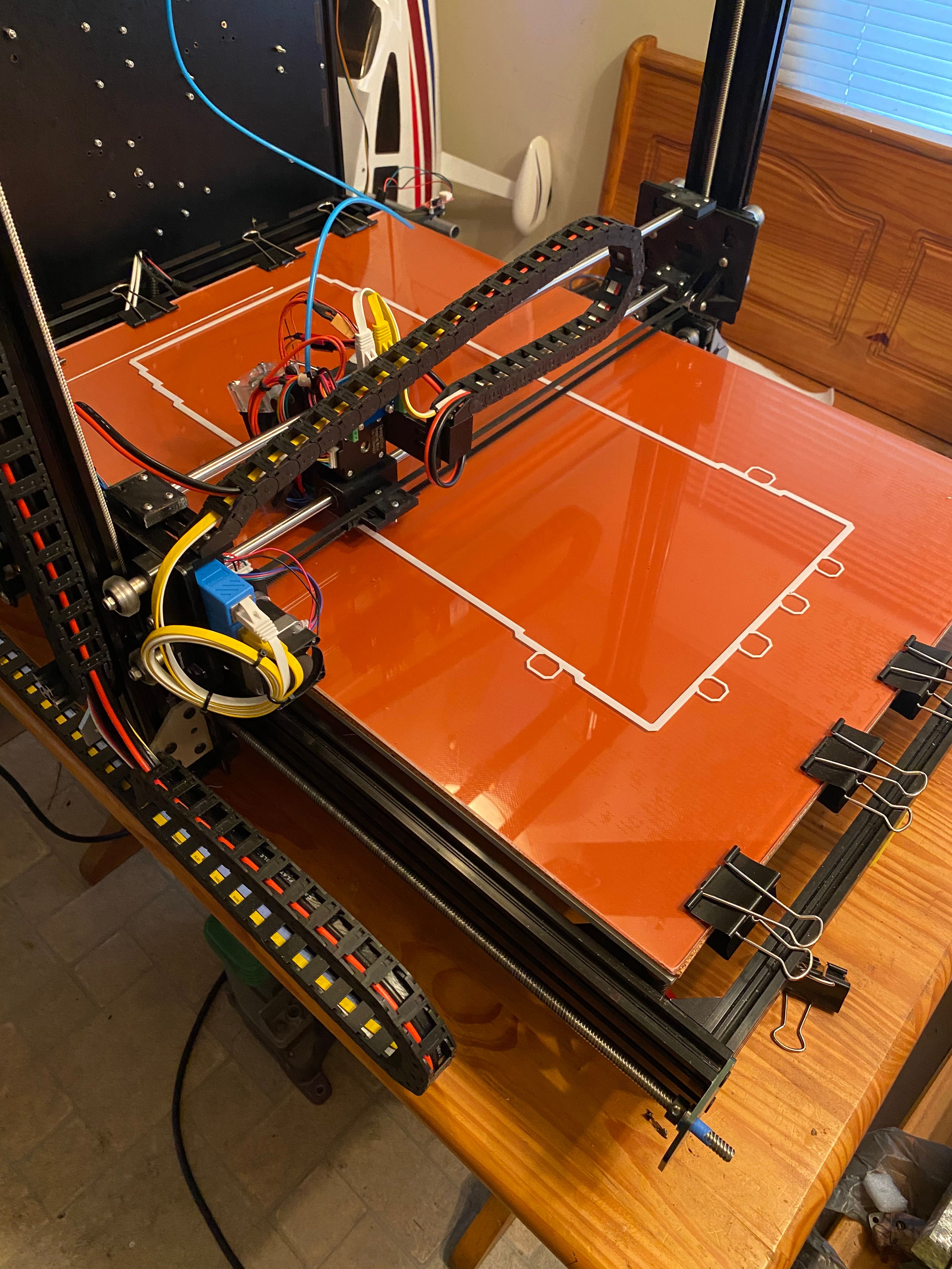
A few of you may recall my large printer build I did. Thanks to all the help here getting the gcode all worked out the printer is printing but its always had a bit of minor ringing in it. Im guessing a lot is just due to my design as i'm no engineer, but also a lot has to do with the table its on not being as sturdy as i like but it is what it is for now. Coupled with the sheer size and weight of the printer and not a perfect design, it has ringing.
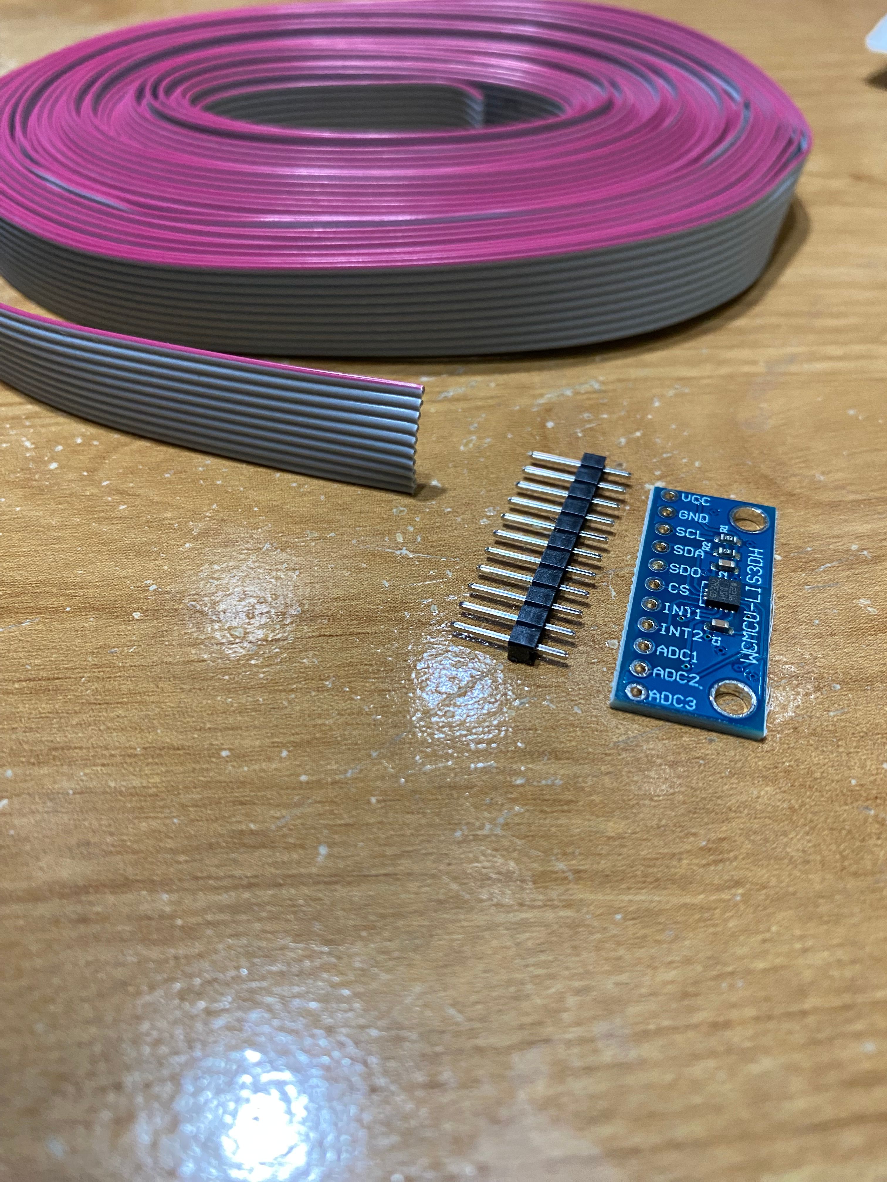
I have decided to try input shaping to try to minimize the ringing. So I have a few questions before I start. I have purchased a few lis3dsh boards and even the adafruit board in case there are any DOA's. I have bought some ribbon cable, and have a dupont connector kit for termination. My question is before i even start, will my required cable length be to long to even attempt this? The cable will need to be in the ballpark of 140 inches in length to get through all my cable chains due to the size of the printer. Can i go through the cable chains or should i just make up a temporary cable just long enough to do the tests then remove afterwards???
The Hardware

The Printer

.
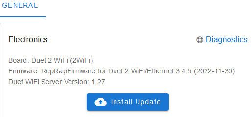
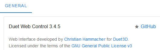
Firmware and DWC Version
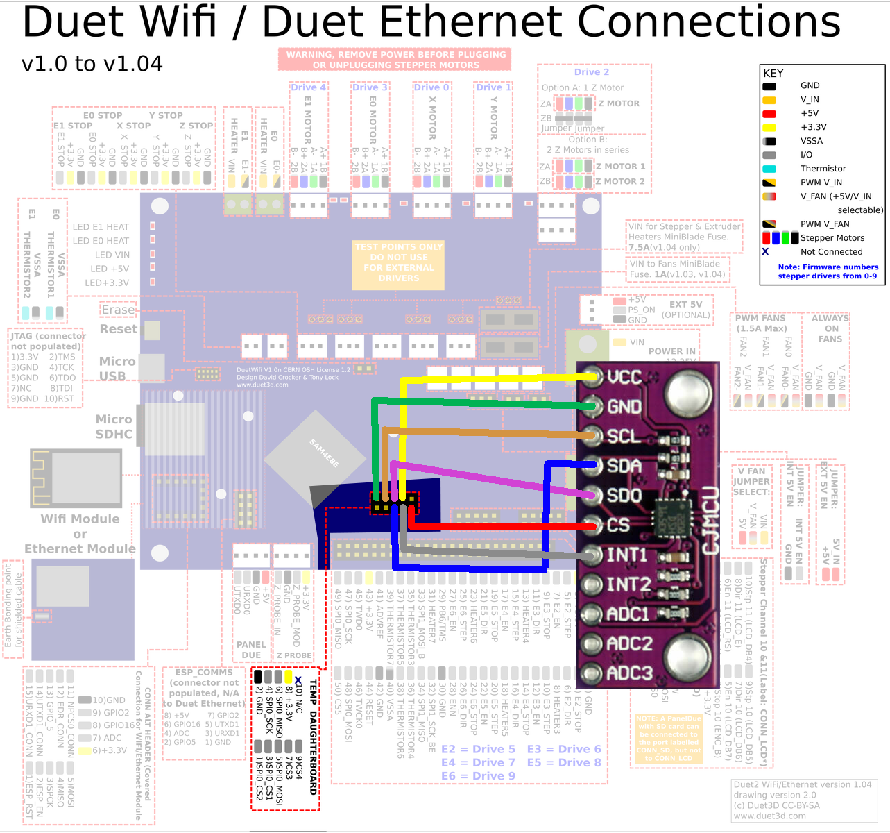
I found this image for wiring in another thread. Is this accurate? I have a duet wifi2 with the expansion board.
My Layout

-
Ribbon cable of that length will be subject to interference. I would suggest getting a USB3 extension cable on amazon and clipping the ends and using as short a length as you can. Keep in mind it only needs to be mounted for measuring, not during normal use.
-
@Phaedrux
If it only has to be temporary then I will use the ribbon and bypass the cable chains I guess.
I will try to find time to do that this weekend. Then I will try to get the necessary Gcode added.