Problem with the chamber's PT1000 thermistor
-
Hi everybody.
I have had a problem with the PT1000 thermistor that I have installed for the chamber.
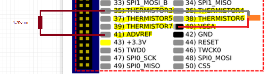
As soon as I connect it to the thermistor3(pin35) and the VSSA(40) the temperature it indicates begins to drop very slowly from 2000ºC until it stabilizes at a temperature much higher than the real one.
I have tried to put a 4.7KΩ resistor between ADVREF and thermistor3 in case that was the problem, but the same thing keeps happening.
I don't know if to connect the PT1000 to the expansion pins it is necessary to connect them in a different way, to those of the hot bed and the extruders, or if they have to be configured in another way.
I attach a graph of the temperature that it measures and how it stabilizes over time, a diagram of the connections that I have made, and the lines of the program referring to this thermocouple.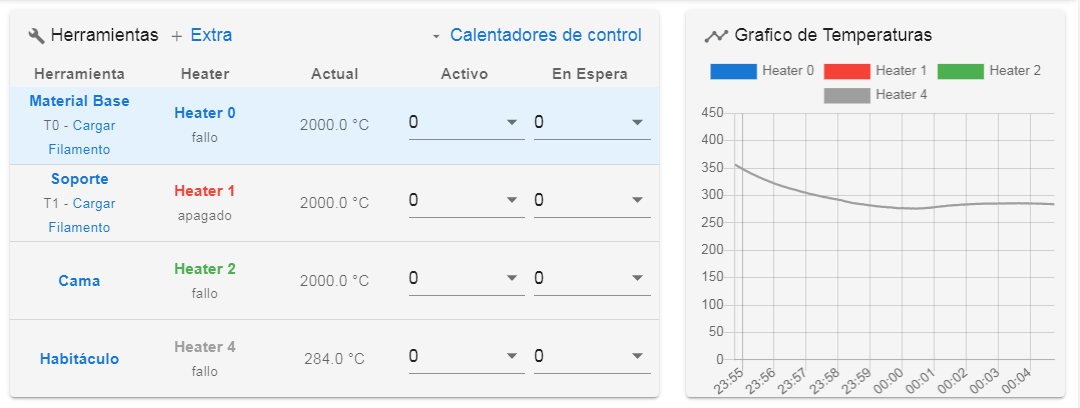
M308 S3 P"e3temp" Y"pt1000" R4700
M950 H3 C"exp.heater3" T3
M307 H3 B0 S1.00
M141 H3
M143 H3 S90Thank you very much in advance for your help.
-
@Juan-Estanislao Your wiring looks correct compared how the other temperature sensors are wired on the Duet 2 WiFi schematic. Check that you have the wires on the expansion connector plugged in in the correct place. I'm a bit confused why your heater shows as 'Heater 4' rather than 'Heater 3', though. Can you post your full config.g? Also send
M98 P"config.g", andM115and post the responses.Ian
Bed-slinger - Mini5+ WiFi/1LC | RRP Fisher v1 - D2 WiFi | Polargraph - D2 WiFi | TronXY X5S - 6HC/Roto | CNC router - 6HC | Tractus3D T1250 - D2 Eth
-
@droftarts thank you very much for your answer.
Sorry for the confusion of the "Heater 4" image. The image is taken from a test I did before changing it to "Heater 3" but the problem is the same on all pins.
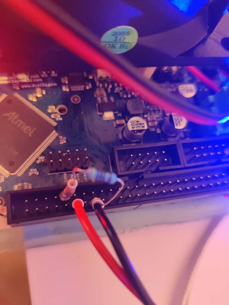
I post the entire config.g changed to "Heater 4" to match the image.code_text ; Configuration file for Duet WiFi (firmware version 3.3) ; executed by the firmware on start-up ; ; generated by RepRapFirmware Configuration Tool v3.3.15 on Thu Nov 24 2022 23:03:50 GMT+0100 (hora estándar de Europa central) ; General preferences M575 P1 S1 B57600 ; enable support for PanelDue G90 ; send absolute coordinates... M83 ; ...but relative extruder moves M550 P"Estanisleitor 2P" ; set printer name ; Network M552 S1 ; enable network M586 P0 S1 ; enable HTTP M586 P1 S0 ; disable FTP M586 P2 S0 ; disable Telnet ; Drives M569 P0 S1 ; physical drive 0 goes forwards M569 P1 S1 ; physical drive 1 goes forwards M569 P2 S0 ; physical drive 2 goes forwards M569 P3 S1 ; physical drive 3 goes forwards M569 P4 S1 ; physical drive 4 goes forwards M584 X0 Y1 Z2 E3:4 ; set drive mapping M350 X16 Y16 Z16 E16:16 I1 ; configure microstepping with interpolation M92 X239.80 Y239.80 Z2414.00 E362.80:362.80 ; set steps per mm M566 X900.00 Y900.00 Z400.00 E120.00:120.00 ; set maximum instantaneous speed changes (mm/min) M203 X6000.00 Y6000.00 Z400.00 E1200.00:1200.00 ; set maximum speeds (mm/min) M201 X200.00 Y200.00 Z20.00 E250.00:250.00 ; set accelerations (mm/s^2) M906 X1700 Y1700 Z1700 E1100:1100 I30 ; set motor currents (mA) and motor idle factor in per cent M84 S30 ; Set idle timeout ; Axis Limits M208 X-45 Y0 Z0 S1 ; set axis minima M208 X480 Y393 Z406 S0 ; set axis maxima ; Endstops M574 X1 S1 P"xstop" ; configure switch-type (e.g. microswitch) endstop for low end on X via pin xstop M574 Y2 S1 P"ystop" ; configure switch-type (e.g. microswitch) endstop for high end on Y via pin ystop M574 Z2 S1 P"zstop" ; configure switch-type (e.g. microswitch) endstop for high end on Z via pin zstop :Z-Probe M950 S0 C"exp.heater3" M558 P9 C"^zprobe.in" H5 F120 T6000 ; FW v3 BLTouch connected to Z probe IN pin M558 H30 ;*** Remove this line after delta calibration has been done and new delta parameters have been saved G31 P500 X-32 Y13 Z2.9 ; Set Z probe trigger value, offset and trigger height M557 X20:400 Y30:350 S50 ; Define mesh grid M915 X Y S5 R2 M950 H3 C"nil" ; Disable heaters H3-H7 to free up pins ; Heaters M308 S0 P"e0temp" Y"pt1000" ; configure sensor 0 as PT1000 on pin e0temp M950 H0 C"e0heat" T0 ; create nozzle heater output on e0heat and map it to sensor 0 M307 H0 B0 S1.00 ; disable bang-bang mode for heater and set PWM limit M143 H0 S450 ; set temperature limit for heater 0 to 450C M308 S1 P"e1temp" Y"pt1000" ; configure sensor 1 as PT1000 on pin e1temp M950 H1 C"e1heat" T1 ; create nozzle heater output on e1heat and map it to sensor 1 M307 H1 B0 S1.00 ; disable bang-bang mode for heater and set PWM limit M143 H1 S450 ; set temperature limit for heater 1 to 450C M308 S2 P"bedtemp" Y"pt1000" ; configure sensor 2 as PT1000 on pin bedtemp M950 H2 C"bedheat" T2 ; create bed heater output on bedheat and map it to sensor 2 M307 H2 B0 S1.00; disable bang-bang mode for the bed heater and set PWM limit M570 H2 P1200 T70 ; comando añadido porque tarda mucho en calentar la cama y daba error M140 H2 ; map heated bed to heater 2 M143 H2 S180 ; set temperature limit for heater 2 to 180C M308 S4 P"e4temp" Y"pt1000" R4700 ; configure sensor 4 as PT1000 on pin duex.e4temp M950 H4 C"exp.heater4" T4 ; create chamber heater output on duex.e4heat and map it to sensor 4 M307 H4 B0 S1.00 ; disable bang-bang mode for the chamber heater and set PWM limit M141 H4 ; map chamber to heater 4 M143 H4 S90 ; set temperature limit for heater 4 to 90C ; Fans M950 F0 C"fan0" Q500 ; create fan 0 on pin fan0 and set its frequency M106 P0 C"Ventilador De Pieza" S0 H-1 ; set fan 0 name and value. Thermostatic control is turned off M950 F1 C"fan1" Q500 ; create fan 1 on pin fan1 and set its frequency M106 P1 C"Ventilador De Cabezal" S1 H-1 ; set fan 1 name and value. Thermostatic control is turned off M950 F2 C"fan2" Q500 ; create fan 2 on pin fan2 and set its frequency M106 P2 C"Ventilador De Cámara" S0 H2 T90 ; set fan 2 name and value. Thermostatic control is turned on ; Tools M563 P0 S"Material Base" D0 H0 F1 ; define tool 0 G10 P0 X0 Y0 Z0 ; set tool 0 axis offsets G10 P0 R0 S0 ; set initial tool 0 active and standby temperatures to 0C M563 P1 S"Soporte" D1 H1 F1 ; define tool 1 G10 P1 X38 Y0 Z0 ; set tool 1 axis offsets G10 P1 R0 S0 ; set initial tool 1 active and standby temperatures to 0C ; Custom settings are not defined M591 D0 P2 C"e0stop" S1 ; Final de Filamento extrusor 0 M591 D0 P2 C"e1stop" S1 ; Final de Filamento extrusor 1 ; Miscellaneous M501 ; load saved parameters from non-volatile memory M911 S10 R11 P"M913 X0 Y0 G91 M83 G1 Z3 E-5 F1000" ; set voltage thresholds and actions to run on power loss T0 ; select first tool G10 P1 R0 S0 ; set initial tool 1 active and standby temperatures to 0C ; Custom settings are not definedI include a photo of the provisional connection to verify that the pins are correct, I think so.
Below I indicate the answers obtained by the program:
 .
.On the other hand, to try to identify the error I have measured the voltage between VSSA and the different THERMISTORS and it does not give a constant value of 3.3V. the voltage fluctuates between 0.5V and 3.3V more or less. I don't know if this is normal.
I appreciate your interest.
-
@Juan-Estanislao the voltage between ADVREF and VSSA should always be close to 3.3V, and the voltge between VSSA and GND should always be a small fraction of a volt, provided that the thermistors are not shorted to anything.
You do need to connect a 2K2 or 4K7 resistor between the thermistor input and ADVREF. Without that resistor, you will most likely get slowly changing random readings if no thermistor or PT1000 is connected (similar to what you observed); or a short-circuit error if one is connected.
Duet WiFi hardware designer and firmware engineer
Please do not ask me for Duet support via PM or email, use the forum
http://www.escher3d.com, https://miscsolutions.wordpress.com -
Hi @dc42
The voltages between ADVREF and VSSA are very close to 3.3V and the voltage between VSSA and GND is a small fraction of a volt as you say.
As seen in the photo, I have connected a 4K7 resistor between the thermistor input and ADVREF, but the problem is not solved.
Is it normal that without having anything connected to these pins, the voltmeter measures a voltage between the VSSA pin and THERMISTOR4 that fluctuates between 0.5V and 3.3V more or less? -
@Juan-Estanislao said in Problem with the chamber's PT1000 thermistor:
Is it normal that without having anything connected to these pins, the voltmeter measures a voltage between the VSSA pin and THERMISTOR4 that fluctuates between 0.5V and 3.3V more or less?
No, that's not normal. If nothing is connected to the Thermistor4 pin then a voltmeter connected between that pin and either VSSA or ground would normally read zero. If the voltmeter had an extremely high input resistance, or if there was condensation on the board, then it might read higher.
Duet WiFi hardware designer and firmware engineer
Please do not ask me for Duet support via PM or email, use the forum
http://www.escher3d.com, https://miscsolutions.wordpress.com -
We can then conclude that the duet2wifi is broken.
What a pity.
Thank you very much for clarifying my doubts.
-
@Juan-Estanislao if the reading varies a lot regardless of whether the thermistor and/or 4K7 resistor are connected, then I think the most likely explanation is that the thermistor4 pin on the expansion connector is open circuit, or the 10K series resistor connected to that pin is not properly soldered. Have you tried using a different thermistor input on the expansion connector?
Duet WiFi hardware designer and firmware engineer
Please do not ask me for Duet support via PM or email, use the forum
http://www.escher3d.com, https://miscsolutions.wordpress.com -
@dc42 I have tried all the THERMISTERS of the expansion pins and they all give a reading that fluctuates a lot.
I will measure the resistors on the board and check if they are well soldered. -
I have checked the resistances of the THERMISTORS and they all give a value of 10K.
On the other hand, I have made a measurement of the voltage between the two cables of the PT1000 being connected to the 4K7 resistor between the thermistor input and ADVREF, and it gives a value of 0.68V at room temperature. The exact same value that it gives when connected to BEDTEMP, E1TEMP, and E0TEMP, which I deduce is something either from the chip or from the program.
I don't know if you can see the error in the program. -
I've been trying different things all week but it still doesn't work.
Could you please confirm that the configuration is correct and that the connection with the 4K7 resistor is correct?
If so, I'll buy another duet, if it's a problem with the duet.
Thank you so much. -
@Juan-Estanislao said in Problem with the chamber's PT1000 thermistor:
I have checked the resistances of the THERMISTORS and they all give a value of 10K.
In that case they are not PT1000 sensors. They could be PT10000 sensors, although I have never heard of such a sensor. Most likely they are 10K thermistors. If so then you should configure them like this:
M308 S3 P"e3temp" Y"thermistor" R4700 T10000
Duet WiFi hardware designer and firmware engineer
Please do not ask me for Duet support via PM or email, use the forum
http://www.escher3d.com, https://miscsolutions.wordpress.com -
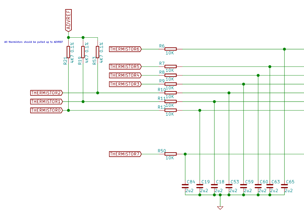
@dc42 I took that as meaning he had checked the 10K series resistors that connect to each thermistor pin, ie R6 to R9 below:
Ian
Bed-slinger - Mini5+ WiFi/1LC | RRP Fisher v1 - D2 WiFi | Polargraph - D2 WiFi | TronXY X5S - 6HC/Roto | CNC router - 6HC | Tractus3D T1250 - D2 Eth
-
@droftarts said in Problem with the chamber's PT1000 thermistor:
I took that as meaning he had checked the 10K series resistors that connect to each thermistor pin, ie R6 to R9 below
That's what I mean. That these resistors are correct and are well soldered.
As explained in the photo that I sent of the connection, I connected the 4K7 resistor between ADVREF and THERMISTOR3,4,5... I did the same configuration that you indicate in the image.
I measured the voltage of the PT1000 at room temperature and it gave 0.68V in a stable way. The same value it gives if I connect the same PT1000 to BEDTEMP, E1TEMP, and E0TEMP. From this I deduce that the connections are well made. For some reason the chip doesn't read the voltage.If the configuration is correct, it is the only reason why it can fail.
-
@Juan-Estanislao Are you sure your resistor is 4K7 ohm? It should be Yellow, Violet, Black, Brown and Green. Slightly hard to see in your picture, but yours looks more like Yellow, Blue, Blue, Violet, Violet? That would be 4.66G ohms! If it's Yellow, Blue, Blue, Brown, Brown, that would be 4K66, which would be close enough.
Otherwise, I'd suspect a bad joint in your wiring, probably the thermistor and/or resistor is not making contact with one of the pins. You can check for continuity by using the pin of the connector on the back of the board.
Ian
Bed-slinger - Mini5+ WiFi/1LC | RRP Fisher v1 - D2 WiFi | Polargraph - D2 WiFi | TronXY X5S - 6HC/Roto | CNC router - 6HC | Tractus3D T1250 - D2 Eth
-
@droftarts The colors of my resistor are yellow, violet, black, brown and brown, because it has a tolerance of 1%. It's 4K7.
The connections are correct. I have measured continuity. And as I said before the voltage between the ends of PT1000 are the same as in BEDTEMP, E1TEMP, and E0TEMP -
@Juan-Estanislao said in Problem with the chamber's PT1000 thermistor:
M308 S3 P"e3temp" Y"pt1000" R4700
The Thermistor3 pin on the expansion connector is not pin "e3temp", it's pin "e2temp". This is because thermistor0 in the Duet 2 is "bedtemp", thermistor 1 is "e0temp", and so on.
Duet WiFi hardware designer and firmware engineer
Please do not ask me for Duet support via PM or email, use the forum
http://www.escher3d.com, https://miscsolutions.wordpress.com -
@dc42 Doh! I can't believe I missed that!
Ian
-
@dc42 That was the problem. I have already changed the pin and it seems that everything is fine and that the measurements are correct.
Thank you very much for your help.
-
 undefined dc42 marked this topic as a question
-
undefined dc42 has marked this topic as solved