Duet3D Logo Duet3D
    • Tags
    • Documentation
    • Order
    • Register
    • Login
    1. Home
    2. Juan Estanislao
    • Profile
    • Following 0
    • Followers 0
    • Topics 2
    • Posts 14
    • Best 0
    • Controversial 0
    • Groups 0

    Juan Estanislao

    @Juan Estanislao

    0
    Reputation
    1
    Profile views
    14
    Posts
    0
    Followers
    0
    Following
    Joined Last Online

    Juan Estanislao Unfollow Follow

    Latest posts made by Juan Estanislao

    • RE: "Warning: Driver 0 stall"

      @oliof I am very sorry that it took me so long to respond to you, but I have not been able to access the printer until today.
      As you requested, I will show you the configuration file.

      Thank you very much for the help.

      ; Configuration file for Duet WiFi (firmware version 3.3)
      ; executed by the firmware on start-up
      ;
      ; generated by RepRapFirmware Configuration Tool v3.3.15 on Thu Nov 24 2022 23:03:50 GMT+0100 (hora estándar de Europa central)

      ; General preferences
      M575 P1 S1 B57600 ; enable support for PanelDue
      G90 ; send absolute coordinates...
      M83 ; ...but relative extruder moves
      M550 P"Estanisleitor 2P" ; set printer name

      ; Network
      M552 S1 ; enable network
      M586 P0 S1 ; enable HTTP
      M586 P1 S0 ; disable FTP
      M586 P2 S0 ; disable Telnet

      ; Drives
      M569 P0 S1 ; physical drive 0 goes forwards
      M569 P1 S1 ; physical drive 1 goes forwards
      M569 P2 S0 ; physical drive 2 goes forwards
      M569 P3 S0 ; physical drive 3 goes forwards
      M569 P4 S1 ; physical drive 4 goes forwards
      M584 X0 Y1 Z2 E3:4 ; set drive mapping
      M350 X16 Y16 Z16 E16:16 I1 ; configure microstepping with interpolation
      M92 X239.65 Y240.15 Z2402.00 E427.9:427.9 ; set steps per mm
      M566 X900.00 Y900.00 Z400.00 E120.00:120.00 ; set maximum instantaneous speed changes (mm/min)
      M203 X6000.00 Y6000.00 Z400.00 E1200.00:1200.00 ; set maximum speeds (mm/min)
      M201 X200.00 Y200.00 Z20.00 E250.00:250.00 ; set accelerations (mm/s^2)
      M906 X1700 Y1700 Z1700 E1100:1100 I30 ; set motor currents (mA) and motor idle factor in per cent
      M84 S30 ; Set idle timeout

      ; Axis Limits
      M208 X-39 Y0 Z0 S1 ; set axis minima
      M208 X462 Y378 Z419 S0 ; set axis maxima

      ; Endstops
      M574 X1 S1 P"xstop" ; configure switch-type (e.g. microswitch) endstop for low end on X via pin xstop
      M574 Y2 S1 P"ystop" ; configure switch-type (e.g. microswitch) endstop for high end on Y via pin ystop
      M574 Z2 S1 P"zstop" ; configure switch-type (e.g. microswitch) endstop for high end on Z via pin zstop

      :Z-Probe
      M950 S0 C"exp.heater3"
      M558 P9 C"^zprobe.in" H3 F300 T6000 ; FW v3 BLTouch connected to Z probe IN pin
      G31 P500 X61.2 Y8.4 Z0.64 ; Set Z probe trigger value, offset and trigger height Incrementar el valor = acercar la mesa de impresión.
      M557 X24:460 Y11:376 S60 ; Define mesh grid
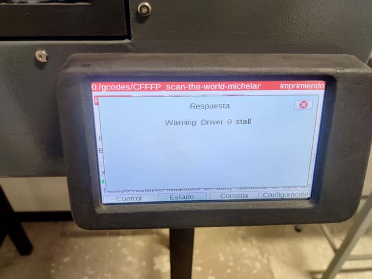
      M915 X Y S5 R2
      M950 H6 C"nil" ; Disable heaters H3-H7 to free up pins

      ; Heaters
      M308 S0 P"e0temp" Y"pt1000" ; configure sensor 0 as PT1000 on pin e0temp
      M950 H0 C"e0heat" T0 ; create nozzle heater output on e0heat and map it to sensor 0
      M570 H0 P400 T400
      M307 H0 B0 S1.00 ; disable bang-bang mode for heater and set PWM limit
      M143 H0 S420 ; set temperature limit for heater 0 to 450C
      M308 S1 P"e1temp" Y"pt1000" ; configure sensor 1 as PT1000 on pin e1temp
      M950 H1 C"e1heat" T1 ; create nozzle heater output on e1heat and map it to sensor 1
      M570 H1 P400 T400
      M307 H1 B0 S1.00 ; disable bang-bang mode for heater and set PWM limit
      M143 H1 S420 ; set temperature limit for heater 1 to 450C
      M308 S2 P"bedtemp" Y"pt1000" R4700 ; configure sensor 2 as PT1000 on pin bedtemp
      M950 H2 C"bedheat" T2 ; create bed heater output on bedheat and map it to sensor 2
      M307 H2 B0 S1.00; disable bang-bang mode for the bed heater and set PWM limit
      M570 H2 P1200 T90 ; comando añadido porque tarda mucho en calentar la cama y daba error
      M140 H2 ; map heated bed to heater 2
      M143 H2 S130 ; set temperature limit for heater 2 to 180C

      Cámara
      M308 S3 P"e3temp" Y"pt1000" R4700 ; configure sensor 3 as PT1000 on pin duex.e2temp
      M950 H4 C"exp.heater4" T3 ; create chamber heater output on duex.e3heat and map it to sensor 3
      M307 H4 B0 S1.00 ; disable bang-bang mode for the chamber heater and set PWM limit
      M570 H4 P4200 T110
      M141 H4 ; map chamber to heater 3
      M143 H4 S70 ; set temperature limit for heater 3 to 90C

      Ventiladores

      Ventilador de pieza
      M950 F0 C"fan0" Q500 ; create fan 0 on pin fan0 and set its frequency
      M106 P0 C"Ventilador De Pieza" S1 H-1 ; set fan 0 name and value. Thermostatic control is turned off

      Bomba de agua y ventilador radiador
      M308 S4 P"e4temp" Y"pt1000" R4700 ; configure sensor 4 as PT1000 on pin duex.e5temp
      M950 F1 C"fan1" Q500 ; create fan 1 on pin fan1 and set its frequency
      M106 P1 C"Ventilador De Cabezal" T60 H4 X1 ; set fan 1 name and value. Thermostatic control is turned on

      Ventilador Filtro Cámara
      M950 F2 C"fan2" Q500 ; create fan 2 on pin fan2 and set its frequency
      M106 P2 C"Ventilador De Cámara" T60 H3 X1 ; set fan 2 name and value. Thermostatic control is turned on

      Ventilador Cabezal soplador
      M308 S5 P"e5temp" Y"pt1000" R4700 ; configure sensor 5 as PT1000 on pin duex.e6temp
      M308 S6 P"e6temp" Y"pt1000" R4700 ; configure sensor 6 as PT1000 on pin duex.e7temp
      M950 F3 C"exp.heater7" Q500 ; create fan 1 on pin fan1 and set its frequency
      M106 P3 C"Soplador Cabezal" T40 H5:6 X1 ; set fan 1 name and value. Thermostatic control is turned on

      Bomba Aire MotorY
      M308 S7 P"e2temp" Y"pt1000" R4700 ; configure sensor 6 as PT1000 on pin duex.e7temp
      M950 F4 C"exp.heater5" Q500 ; create fan 1 on pin fan1 and set its frequency
      M106 P4 C"Bomba Aire MotorY" T50 H7 X1 ; set fan 1 name and value. Thermostatic control is turned on

      ; Tools
      M563 P0 S"Material Base" D0 H0 F1 ; define tool 0
      G10 P0 X0 Y0 Z0 ; set tool 0 axis offsets
      G10 P0 R0 S0 ; set initial tool 0 active and standby temperatures to 0C
      M563 P1 S"Soporte" D1 H1 F1 ; define tool 1
      G10 P1 X38 Y0 Z0 ; set tool 1 axis offsets
      G10 P1 R0 S0 ; set initial tool 1 active and standby temperatures to 0C

      ; Custom settings are not defined

      M591 D0 P2 C"e0stop" S1 ; Final de Filamento extrusor 0
      M591 D0 P2 C"e1stop" S1 ; Final de Filamento extrusor 1

      ; Miscellaneous
      M501 ; load saved parameters from non-volatile memory
      M911 S10 R11 P"M913 X0 Y0 G91 M83 G1 Z3 E-5 F1000" ; set voltage thresholds and actions to run on power loss
      T0 ; select first tool
      G10 P1 R0 S0 ; set initial tool 1 active and standby temperatures to 0C

      ; Custom settings are not defined

      posted in General Discussion
      Juan Estanislaoundefined
      Juan Estanislao
    • RE: "Warning: Driver 0 stall"

      @oliof
      Thank you very much for your answer. Right now I don't have the files, but as soon as I have them I'll buy them without a problem.

      Thank you very much in advance.

      posted in General Discussion
      Juan Estanislaoundefined
      Juan Estanislao
    • RE: "Warning: Driver 0 stall"

      @jens55 Thank you very much for your comment.

      posted in General Discussion
      Juan Estanislaoundefined
      Juan Estanislao
    • "Warning: Driver 0 stall"

      Hello everyone.

      After a lot of work I managed to finish the 3D printer. And everything works correctly, and the prints come out well. The only problem that persists is a message that continually appears on the screen. "Warning: Driver 0 stall"
      This message appears with both driver 0 and driver 1, both motors are the extruders found in the print head.
      This message appears when it has been running for a while.
      Please note that I have heated the chamber.
      Could you please tell me what this message is about?

      On the other hand, could you tell me how I can at least remove the message from the screen? It comes up so many times in a row that I can't use the screen when the message is on the screen.

      Another message that I would like to remove from the screen or make it appear less often is the one that tells me that it is not connected to Wi-Fi.
      Do you know how I can solve this problem?

      Thank you very much for the help.

      IMG_20240225_163901.jpg IMG_20240223_180645.jpg

      posted in General Discussion
      Juan Estanislaoundefined
      Juan Estanislao
    • RE: Problem with the chamber's PT1000 thermistor

      @dc42 That was the problem. I have already changed the pin and it seems that everything is fine and that the measurements are correct.
      Thank you very much for your help.😊

      posted in General Discussion
      Juan Estanislaoundefined
      Juan Estanislao
    • RE: Problem with the chamber's PT1000 thermistor

      @droftarts The colors of my resistor are yellow, violet, black, brown and brown, because it has a tolerance of 1%. It's 4K7.
      The connections are correct. I have measured continuity. And as I said before the voltage between the ends of PT1000 are the same as in BEDTEMP, E1TEMP, and E0TEMP

      posted in General Discussion
      Juan Estanislaoundefined
      Juan Estanislao
    • RE: Problem with the chamber's PT1000 thermistor

      @droftarts said in Problem with the chamber's PT1000 thermistor:

      I took that as meaning he had checked the 10K series resistors that connect to each thermistor pin, ie R6 to R9 below

      That's what I mean. That these resistors are correct and are well soldered.

      As explained in the photo that I sent of the connection, I connected the 4K7 resistor between ADVREF and THERMISTOR3,4,5... I did the same configuration that you indicate in the image.
      I measured the voltage of the PT1000 at room temperature and it gave 0.68V in a stable way. The same value it gives if I connect the same PT1000 to BEDTEMP, E1TEMP, and E0TEMP. From this I deduce that the connections are well made. For some reason the chip doesn't read the voltage.

      If the configuration is correct, it is the only reason why it can fail.

      posted in General Discussion
      Juan Estanislaoundefined
      Juan Estanislao
    • RE: Problem with the chamber's PT1000 thermistor

      I've been trying different things all week but it still doesn't work.
      Could you please confirm that the configuration is correct and that the connection with the 4K7 resistor is correct?
      If so, I'll buy another duet, if it's a problem with the duet.
      Thank you so much.

      posted in General Discussion
      Juan Estanislaoundefined
      Juan Estanislao
    • RE: Problem with the chamber's PT1000 thermistor

      I have checked the resistances of the THERMISTORS and they all give a value of 10K.
      On the other hand, I have made a measurement of the voltage between the two cables of the PT1000 being connected to the 4K7 resistor between the thermistor input and ADVREF, and it gives a value of 0.68V at room temperature. The exact same value that it gives when connected to BEDTEMP, E1TEMP, and E0TEMP, which I deduce is something either from the chip or from the program.
      I don't know if you can see the error in the program.

      posted in General Discussion
      Juan Estanislaoundefined
      Juan Estanislao
    • RE: Problem with the chamber's PT1000 thermistor

      @dc42 I have tried all the THERMISTERS of the expansion pins and they all give a reading that fluctuates a lot.
      I will measure the resistors on the board and check if they are well soldered.

      posted in General Discussion
      Juan Estanislaoundefined
      Juan Estanislao