Angled Printing on Delta Printer
-
I have my machine up and running, but have this mysterious problem.
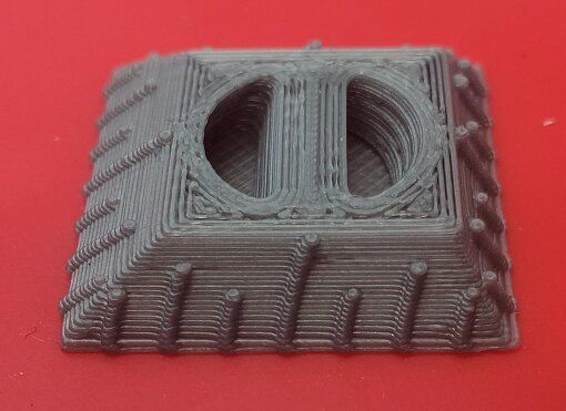
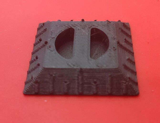
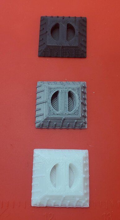
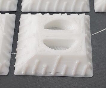
When I grow my parts, the one axis is slanted. (See Pics). ( I printed one good one on my other printer to show what they should look like.)
I have no idea why this is occurring. I have quadruple checked every parameter I can find. I re-sliced, changed settings, tried changing the amperage on the motors in case there was lost steps, but it has no skipping, and everything seems smooth. It is also repeatable, which makes a lost steps issue seem unlikely to me. Has anyone else seen this, or how I may approach troubleshooting this problem?
Thanks in advance.
Gumby(Duet3 Mini+ Wifi, with Smart effector on a delta rig 24v. liquid cooled, zesty nimble extruder)
Here is my config file contents.
; Configuration file for Duet 3 Mini 5+ (firmware version 3.3) ; executed by the firmware on start-up ; ; generated by RepRapFirmware Configuration Tool v3.3.16 on Thu Apr 20 2023 10:24:19 GMT-0400 (Eastern Daylight Time) ; General preferences G90 ; send absolute coordinates... M83 ; ...but relative extruder moves M550 P"Predator" ; set printer name ;M665 X -0.137°, Y 0.131°, Z 0.000° M665 R232.466 L450.7 B185 H408.062 ; Set delta radius, diagonal rod length, printable radius and homed height M666 X0.43 Y-0.05 Z-0.38 ; put your endstop adjustments here, or let auto calibration find them M81 C"!pson" ; allocate the PS_ON pin to power control but leave power off ;M579 X1.0309 Y1.0245 Z.9935 ; Scale Compensation ; Network M552 S1 ; enable network M586 P0 S1 ; enable HTTP M586 P1 S1 ; enable FTP M586 P2 S1 ; enable Telnet ; Drives M569 P0.0 S1 ; physical drive 0.0 goes forwards M569 P0.1 S1 ; physical drive 0.1 goes forwards M569 P0.2 S1 ; physical drive 0.2 goes forwards M569 P0.3 S1 ; physical drive 0.3 goes forwards M584 X0.0 Y0.1 Z0.2 E0.3 ; set drive mapping M350 X16 Y16 Z16 E16 I1 ; configure microstepping with interpolation M92 X160.00 Y160.00 Z160.00 E5700 ; set steps per mm M566 X3000.00 Y3000.00 Z3000.00 E36.00 ; set maximum instantaneous speed changes (mm/min) M203 X18000.00 Y18000.00 Z18000.00 E1800.00 ; set maximum speeds (mm/min) M201 X8000.00 Y8000.00 Z8000.00 E120.00 ; set accelerations (mm/s^2) M906 X1200 Y1200 Z1200 E500 I30 ; set motor currents (mA) and motor idle factor in per cent M84 S30 ; Set idle timeout M591 D0.3 P2 C"io5.in" S1 ; filament monitor connected to E0 endstop M591 D0.3 ; display filament sensor parameters for extruder drive 0 M376 H30 ; Taper mesh comp over 30mm of distance from Zero. ; Axis Limits M208 X-9999:9999 Y-9999:9999 Z-9999:9999 ; set axis minima and maxima ; Endstops M574 X1 S1 P"io6.in" ; configure switch-type (e.g. microswitch) endstop for high end on X via pin io0.in M574 Y1 S1 P"io1.in" ; configure switch-type (e.g. microswitch) endstop for high end on Y via pin io1.in M574 Z1 S1 P"io2.in" ; configure switch-type (e.g. microswitch) endstop for high end on Z via pin io2.in ; Z-Probe M558 P8 R0.4 C"io3.in+io3.out" H5 F1200 T6000 ; set Z probe type to effector and the dive height + speeds ;M558 H30 ;*** Remove this line after delta calibration has been done and new delta parameters have been saved G31 P100 X0 Y0 Z-0.1 ; set Z probe trigger value, offset and trigger height M557 R185 S40 ; define mesh grid ; Heaters M308 S0 P"temp0" Y"thermistor" T100000 B4138 ; configure sensor 0 as thermistor on pin temp0 M950 H0 C"out0" T0 ; create bed heater output on out0 and map it to sensor 0 M307 H0 R0.399 K0.380:0.000 D1.32 E1.35 S1.00 B0 ; disable bang-bang mode for the bed heater and set PWM limit M140 H0 ; map heated bed to heater 0 M143 H0 S120 ; set temperature limit for heater 0 to 120C M308 S1 P"temp1" Y"thermistor" T100000 B4138 ; configure sensor 1 as thermistor on pin temp1 M950 H1 C"out2" T1 ; create nozzle heater output on out1 and map it to sensor 1 M307 H1 R2.382 K0.347:0.000 D6.45 E1.35 S1.00 B0 ; disable bang-bang mode for heater and set PWM limit M143 H1 S300 ; set temperature limit for heater 1 to 300C ; Fans M950 F0 C"out5" Q500 ; create fan 0 on pin out5 and set its frequency M106 P0 S0 H-1 ; set fan 0 value. Thermostatic control is turned off M950 F1 C"out6" Q500 ; create fan 1 on pin out6 and set its frequency M106 P1 S1 H1 T45 ; set fan 1 value. Thermostatic control is turned on ; Tools M563 P0 D0 H1 F0 ; define tool 0 G10 P0 X0 Y0 Z0 ; set tool 0 axis offsets G10 P0 R0 S0 ; set initial tool 0 active and standby temperatures to 0C ; Custom settings are not defined ; Miscellaneous M575 P1 S1 B57600 ;Panel Due enable command T0 ; select first tool -
What happens if you jog Z over the full height range - does the nozzle move purely vertical or have a lateral offset with height??
It's not likely, but the only things I can think of are a stepper with a different physical step count, or a pulley with a different size?
-
@gumby
Could it be caused by effector tilt during calibration? Is the wiring loom to the effector too tight/short to reach each probe point without strain?Side note: It seems you have to print many of these things? Their shape would be perfect for moulding, IMHO.
-
It seems like it may be mechanical.
I have been trying several more fixes and will post when I come to some sort of conclusion in case it helps someone else.
Cheers,
Gumby -
I changed a lot of variables, but it seemed to boil down to reducing acceleration and maximum instantaneous speed change.
It has introduced corner blobs, but now I will try to dial in pressure advance and accelerometer tuning.
So thanks for helping me work the issue out.
Cheers,
Gumby -
@gumby I'm glad you resolved it. It looks like your machine was skipping steps. You might like to check what maximum speeds you can expect before motor torque starts to drop, using the calculator at https://www.reprapfirmware.org/emf.html.
Your M566 XYZ jerk settings were particularly high (3000). Values of 600 to 900 are usual. They only need to be high enough for curves to print smoothly.