Installation of a thermocoupler
-
Hi everyone, hope your doing great!!
I've been given a thermocoupler K1000, with what appear to be a third-party board or maybe the board is simply old? I dunno, but it is supposed to work, which is the important part!! I should receive it in few days so I'll be able to confirm the board model then. Anyway, I proactively did some research and found all the information I needed, except one thing about the capacitor...
Here, dc42(administrator) said in 2017: " The mod consists of adding a 0.01uF ceramic capacitor between each thermocouple terminal and ground."
https://forum.duet3d.com/topic/1270/thermocouple-issues/13
And by searching more, I found that one: "If you purchased a third-party thermocouple interface board, check that there is a 10nF or greater capacitor in parallel with the thermocouple terminals."
https://docs.duet3d.com/User_manual/Connecting_hardware/Temperature_connecting_thermocouples
If the board is a Duet, I assume it will have the capacitor. Or maybe not... In any case, I'll look for them on the board and if they aren't, here come my question:
Does a 0,1uf would do the trick ? dc42 suggest a 0,01uf(10nf) and in the manual it is recommended to install a capacitor with "at least" 0,01uf, which open the door to a bigger one, but how much bigger is my main concern.
I already have plenty of common 104 ceramic capacitor on hand(0,1uf) and few 103Z(0,01uf), but they are +80%/-20% tolerance and I don't know if they would be good enough for such application.
Any info or input would be greatly appreciated

thanks
-
@ReVeRb yes a 0.1uF capacitor should be OK in this position.
-
@ReVeRb Hi dc42, glad to hear from you!

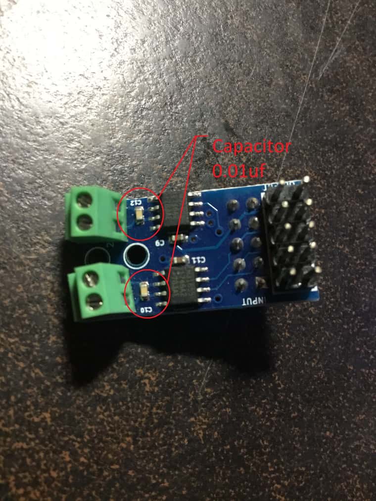
I finally get the board. it's tiny, but I can read on the back:
MAXTempTC v0.2
K Thermocouple Board
Design by: ...
...
...
www.Duet3d.comSo I assume it's a OEM part, is that correct ?
If so, since it's the v0.2 I can assume the capacitors are already on it, is that correct ?
I joined a photo of it.

Should I consider adding a shield too or is it enough to deal with the problem ? The thermocoupler will have approximately 2 inch(or more) of distance mostly everywhere. Except from the thermocouple to the connexion(under the effector) but this part is shilded.
-
@ReVeRb yes the capacitors are already there.
In later versions of the thermocouple board we also added capacitors between each input and the ground plane.
If you are not getting good readings from the thermocouple, check that the thermocouple wires are electrically isolated from the case of the thermocouple.
-
I was having spike all around, so I changed the entire wire for an insulated wire (strainless braided). Which mean, from the thermocoupler to the effector, it's a k-type, stainless braided wire and from the effector to the Duet2, same thing. I still have spike all around.
I've checked the isolation of the thermocouple from it's casing and there is continuity, which mean the probe inside the casing is touching the case... isn't supposed to be like that to allow thermal transfer(since air is an isolation by itself).
I've tested an other model of K-type thermocoupler and it also has the same conductivity between the thermocouple and it's casing. Isn't normal?
What should I expect it to be ?
Is there a model you can recommend that is electricaly isolated ?
Note that my printer is a Delta, with a semi-floading stepper for the extruder. And the signal that "pollute" my thermocoupler is when there is a retraction/pression of that stepper, so I pick-up the magnetic flux from it's wiring, despite the fact that all the wiring of the thermocouple is stainless braided.
Also, starting the heatsink fan or the cooling fan doesn't create spike, neither the heater (I've tested them all), which lead me to ask: If all these doesn't interfere with the thermocoupler (specially the heater), how can the thermocoupler(non-isolated) be affected by the extruder stepper and not by the heater nor the fans ?
I'll try to remove the thermocouple wire from the sleeve spiral wrap and see if it pick up the stepper signal again, if so, maybe it pick up electromagnetic flux from the motherboard ? <-- is that even possible ?
Sorry for the long text, I shoot in every direction, trying to figure out the cause...
Any input/advice are welcomed!
Side note: I finished a print of 3h30 and have no problem. There was spike(+/- 45 to 60sec interval), more or less, but still I was able to print and the temp was always spot on (+/- 0,3 °C), which is "normal" for me condition here.
-
@ReVeRb said in Installation of a thermocoupler:
Is there a model you can recommend that is electricaly isolated ?
Yes, the E3D one is, https://e3d-online.com/products/type-k-thermocouple-cartridge?_pos=2&_sid=8713d02ff&_ss=r.
-
Ok, sorry for the delay. I had a lot of stuff going on, but I came back to say that it work like a charm.
I ordered the thermocoupler you mentioned and instead of passing it's wire in the looming with all other wire, I decided to install it in parallel.(didn't take a chance)
It work amazingly well to be honest, the reading is spot on and precise.
Thanks.
By the way, I don't know how to tag this post as "solved". Can you explain it to me so I can do it. ?
Big thanks dc42, your help is always efficient!!

-
@ReVeRb I'm glad it's working. To mark as solved, click the Topic Tools button and select Ask As Question. Then click it again and select Mark As Solved.
-
 undefined Phaedrux marked this topic as a question
-
 undefined Phaedrux has marked this topic as solved
-
 undefined Inlinebrother referenced this topic