Yaskawa Servo Drive Connection Development
-
I'm working on a build using Yaskawa servos with SGD7S drives, and I have some questions. I plan to use a 6XD mainboard, and I'm starting design of a PCB (my first one, so bear with me...) to streamline connections between the 6XD and the drives. Assuming I keep all the magic smoke in, I'm happy to share the final product with anyone looking to use similar drives.
Question 1: "Servo ON". The "Servo ON" inputs are 24V, opto-isolated, w/4.7kOhm resistors. So, they should be 5milliamp. Can the 6XD's EN(-) pins handle this, or are they only 5V tolerant?
If they do tolerate 24V, could they also handle 3 parallel inputs; 15milliamp at 24V? There are separate forward/reverse prohibits which also need to be pulled on, otherwise the servo will be enabled/on, but not permitted to move. It would be easiest to just link them all, and control all three with EN(-).
Question 2: Step/Dir voltage. The drives want 3.3V inputs for step/dir, not 5V. Based on the wiring schematic, 100ohm resistors on DO_Step(-) and DO_Dir(-) would correct the voltage. Would adding these resistors adversely effect rise/fall times? The drivers want ≤ 0.025μs rise/fall on step/dir signals. I realize the step/dir signals could be sourced from 3.3V, but I'd prefer the resistors if they work. (I started a thread with this specific question earlier, but the questions are already branching out and may continue to do so as this build progresses, so I thought a generalized thread would be more appropriate.)
Thanks for any assistance!
-
@Maestro Did you see the docs for the 6XD? https://docs.duet3d.com/en/Duet3D_hardware/Duet_3_family/Duet_3_Mainboard_6XD_Hardware_Overview
I reckon a voltage divider to reduce the 5V output voltage to 3.3V won't have an effect on the timing as it's just a resisitve load.
-
@chrishamm I have been through the 6XD hardware overview; I did not see anything that addressed these questions. The external driver voltage is marked as "5V nominal", but that doesn't seem to definitively answer the question of whether the EN(-) pin is 24V tolerant, since it's expected to be pulling the driver 5V supply, and 24V would not be an expected use case. If nobody can say otherwise, I guess I have to proceed under the assumption that the EN(-) pin cannot accept 24V, but it would be nice to not be assuming.
My--admittedly layman-- understanding was that resistors did affect rise times, and that they were often used specifically for the purpose of slowing rise times down, to reduce EM radiation when the faster rise is not needed? Are the step/dir signals not high frequency enough--or rising so much faster than 0.025μs already--for this to be a concern?
-
Alright, I've been down a lot of rabbit holes, hopefully learned a few things, and have a draft layout.
Here's all the background:
Drive's IO connection overview:
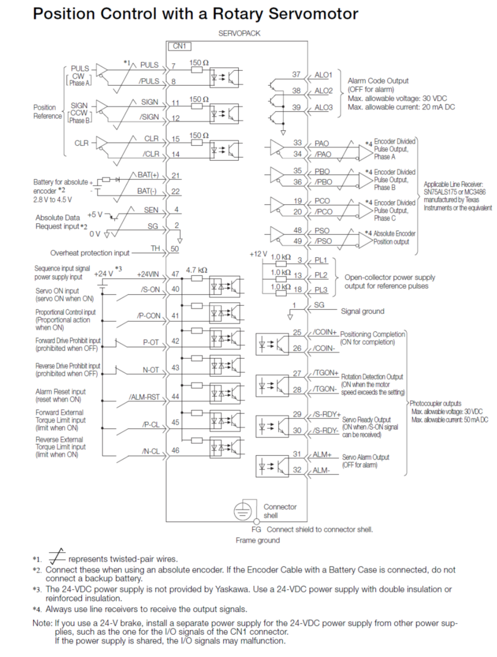
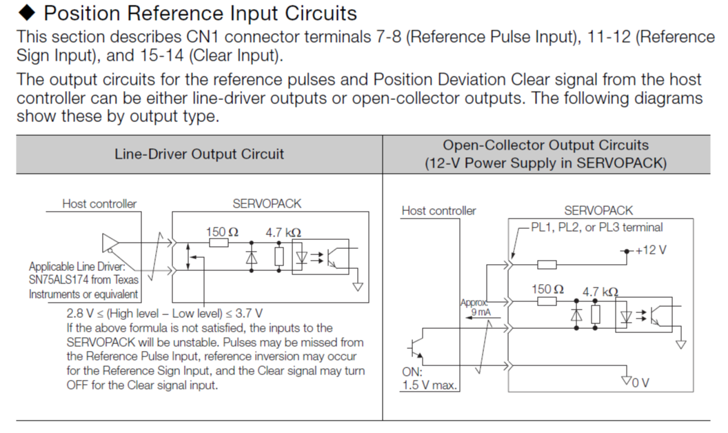
Referring specifically to the Pulse and Direction/Sign inputs
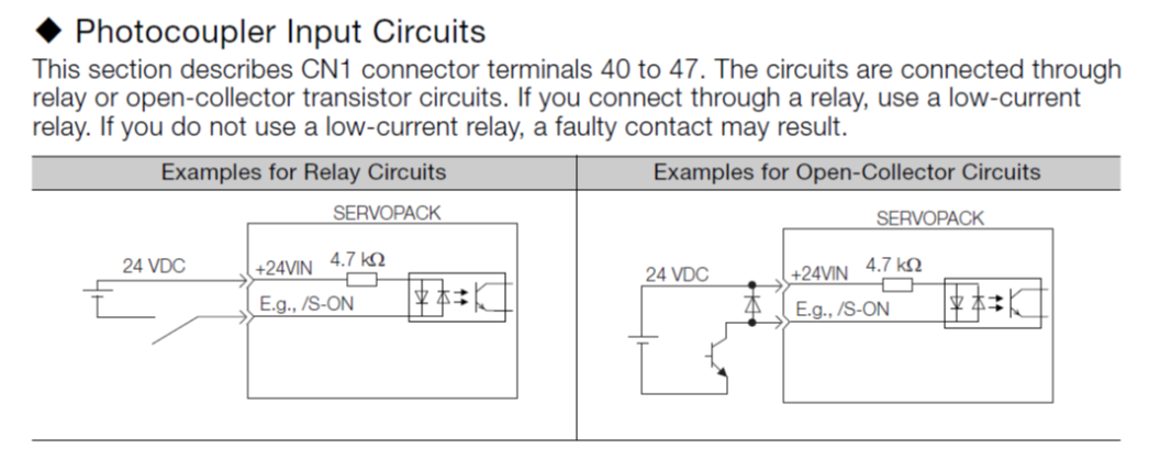
Referring to the servo-on, prohibit, alarm reset, and torque limit inputs
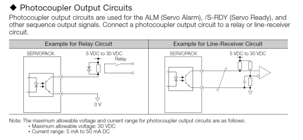
Referring to the alarm output
The full driver manual can be found here, but it's over 600 pages, so I thought I'd paste the highlights above.
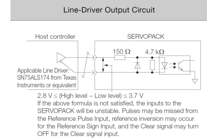
I had previously seen only the line-driver output circuit, but then I found the paired line vs open-collector diagram. That led to the understanding that the 6XD uses open-drain outputs. So, I think the answer to the series resistor question is "no" on the 6XD, because that was wasn't a line-output to start with. There's another figure not pasted here about the caveats with open-collector circuits. Not pasted here because I decided to pivot towards a pair of 1XD boards connected to a 6HC. So, really counting on the temporary nature of the "no input shaping on expansion board motors" limitation!
Here is my current understanding/draft (let's call it v0.1) of the proper connections between a single 1XD and a single SGD7S drive. Disregard the part number on the mosfet; it's a placeholder at this point (I'd be happy for a suggested part if someone wants to save me the research!).
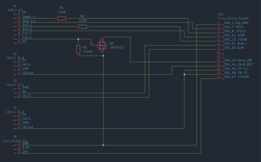
Rundown: The driver circuit provides step/dir/enable, io0.out provides alarm reset, io1.in.1 receives alarm signal, and in2.out can activate torque limiting. The prohibit circuits can be disabled in setup (i.e., "servo on" is all the "on" you need), so I decided not to wire for them.
So, calling anyone who actually understands this stuff for feedback! Components missing? Miswires? Additional functionality that could be added?
Apologies if there are any schematic conventions being trampled on; this is my first foray into KiCad. Many thanks for any input!
-
Well, already I found one problem. The above schematic seems to satisfy the drivers' 3.3V step/dir requirement, however the current would be nearly 20mA, and the 1XD's current limit is 10mA.
So, mmm, I dunno. I'll be back...
-
@Maestro for the step and direction inputs, driving then from a 6XD through 100 ohm series resistors should work. The 6XD enable outputs are not 24V tolerant. However, as they are servos you might decide that enabling/disabling the motors individually is not required and you could use one of the optically isolated outputs as an enable signal instead. It wouldn't be automatic so you would have to enable them using commands in config.g or in your homing files, and disable them if required in stop.g.
Alternatively you could use a resistor and NPN transistor or mosfet to convert the Enable output to be 24V tolerant.
HTH David
Duet WiFi hardware designer and firmware engineer
Please do not ask me for Duet support via PM or email, use the forum
http://www.escher3d.com, https://miscsolutions.wordpress.com -
@dc42 Thanks for the input, David, I appreciate it. Good news on the resistors, less so on the enable, but not unexpected.
Since I'm planning to go to the trouble of making a breakout board already, a few components to allow the use of the dedicated enable signals seems worthwhile, so I'll head down that path.
And since the current capacity of the 6XD's drivers is a better match for the servo drives, I'll go back to the route of a 6XD board, rather than 1XD.
-
@Maestro the 6XD also supports higher step rates than the 1XD, so that is another reason to use it.
Duet WiFi hardware designer and firmware engineer
Please do not ask me for Duet support via PM or email, use the forum
http://www.escher3d.com, https://miscsolutions.wordpress.com -
@dc42 Yes, I did see that. And I was trying not to fall into the more steps = automatically better trap. But, let's face it, it is...
I think I have only one question remaining. For the error input pins, I'm looking at the 6XD schematic files and I can't work out whether additional protection is needed to connect from +5V to the alarm-out optocoupler and back to Dx_ERR(-). Unlike all the other connections, the drive's alarm-out has no current-limiting resistor (see final, "Photocoupler Outputs" reference image above), so I had originally put a 500ohm resistor on Dx_ERR(-), but now wonder if this is unneeded, or should be a lower resistance of ~250ohm?
-
@Maestro you can connect the alarm phototransistor output directly to the alarm input on the Duet (ALM+) and ground on the same connector (ALM-).
Duet WiFi hardware designer and firmware engineer
Please do not ask me for Duet support via PM or email, use the forum
http://www.escher3d.com, https://miscsolutions.wordpress.com -
Thanks @dc42 , that makes things one resistor simpler.
-
Well, it now exists.
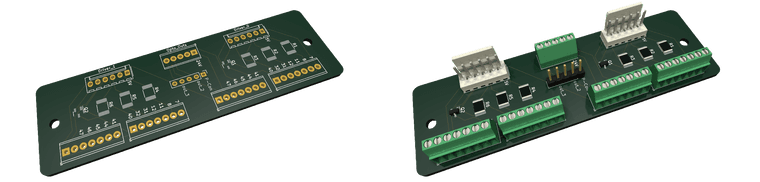
All truly necessary functions can be controlled with the 6XD driver inputs and +24V. With two opto-outs, alarm reset and torque-limiting can also be controlled, and two additional opto-outs can jumper-select between addressing P-Control mode or one of two free breakout pins for user-selected functions.
A GitHub repo has been set up with readme, schematic file, and pcb file. There are a lot of used Yaskawa drives out there; maybe this will help some people who want to try the servo route.
Thanks @dc42 and @chrishamm for the help!
-
@Maestro looks good!
FWIW in designing the 6XD we made provision to attach a daughter board over the driver output connectors, to allow for converting the signals for drivers that wanted differential drive or 24V drive.
Duet WiFi hardware designer and firmware engineer
Please do not ask me for Duet support via PM or email, use the forum
http://www.escher3d.com, https://miscsolutions.wordpress.com -
@dc42 Gah! I saw those holes in the 6XD board by the drivers and was wondering what one would mount there. I don't know how I didn't put two and two together. Well, there may be a daughterboard version coming in the near future!