5 Bar Parallel Scara Workmodes - CNC plasma cutter
-
@NortonAntivirus I'll make a big post in a few days about CoreXY 5 axis together with the information to use it with robot kinematics (configuration, homing, samples with FullControl).
-
@NortonAntivirus a word to belt based gears. I don't like the 12 teeth pulley much, because they are at the limit (low number of teeth engaged, only 5 mm boring possible, high belt stress by low radius). Voron printers use 80 teeth pulleys, so 80 teeth pulleys are available now in growing number. So a 16/80 teeth based gear (or 20/80 for lower ratio) will be probably better. I'll probably change to this combination in the future.
-
@NortonAntivirus ok, final comment
") about the belt gear: I prefer short belts, because I expect better behaviour regarding tension. In this case I want to validate that the kinematics calculates AC offsets correctly. This is the reason for the big distance. I'm using the stepper as counterweight, so the force to rotate the A axis is lower.
about the belt gear: I prefer short belts, because I expect better behaviour regarding tension. In this case I want to validate that the kinematics calculates AC offsets correctly. This is the reason for the big distance. I'm using the stepper as counterweight, so the force to rotate the A axis is lower. -
@JoergS5 Hi again Joerg, I am continuing to make progress and have been testing some Harmonic drives (which seem great so far). I am looking into fixing my Plasma cutter head to the Scara, however I was wondering if its possible to set a cantilevered offset in both X and Y. Currently the 'hotend' can be either in the centre of the two distal joints or an extension of the left or right sides, is it instead possible to have an offset that is a combination of both? I am basically trying to offset my 'hotend' like follows.
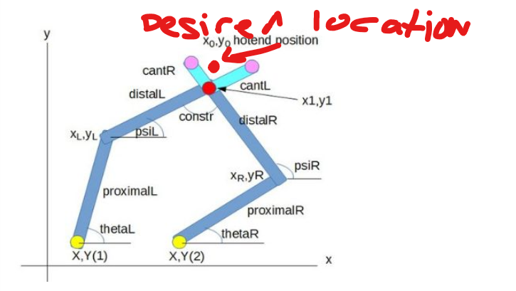
Many thanks -
@NortonAntivirus the XY steppers change XY, but they rotate the endpoint by the Z axis as well. That's the reason why an offset as you wish, tool offsets and mesh compensation offset (of the BLTouch and similar) are not supported in this version.
There is a solution in sight, the robot kinematics, which I am currently working on. 5 bar scara will be supported for 5 axis (but for 3 axis also). It supports whishes like yours, because it calculates positions and orientation for all cases. I've added a short documentation chapter "Five bar parallel Scara 5 axis" at https://docs.duet3d.com/en/User_manual/Machine_configuration/robot_5_axis_CNC , explaining the specifics of the 5 bar kinematics.
-
@JoergS5 Thank you for the response, in this case I shall try to design the tool location to be in the hotend positions listed in the documentation, then maybe in future I can try to implement the Robot CNC 5 Axis methods
Kind Regards
Olly -
@NortonAntivirus that's a good strategy.
For users who want to use mesh compensation with a probe with offset, I have an idea: place the BL Touch to a cantilevered position, home to this position (ie the BL Touch is the endpoint), create mesh, correct the coordinates by the offset in the csv file, home to the endpoint, use mesh.
-
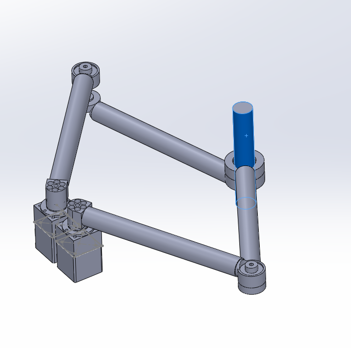
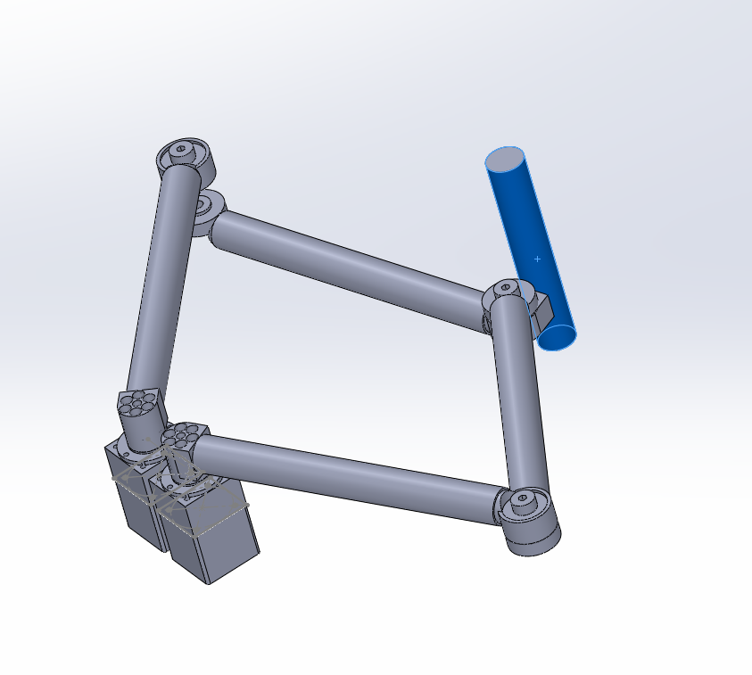
@JoergS5 Just as another question. My plasma cutter will only work in two axis, X and Y. Is it possible to offset the hotend position in both x and y or does it need to be colinear with one of the distal arms? Im just trying to figure out it my plasma torch can be mounted to the side of the Left Distal arm or if it needs to be mounted where both distal arms intersect. The first image below shows it at the intersect of both distal arms, the second image shows where I would ideally mount it, with an X and Y offset. Is it possible to apply this X and Y offset to the 5 bar parallel scara?
-
@NortonAntivirus i thought this was your original question: xy offset in relation to the distal arms. The answer is that the kinematics doesn't support this calculation. The hotend needs to be on one of the distal arms (= negative cantilevered value, however I've never tested this case), on the hinge of the two distal arms or in the prologation (=cantilevered) of one of the distal arms.
The mathematical reason is, calculations are based on circle intersection calculations, which give coordinates as result, but not the orientation (=angle in XY plane) of the endpoint. This angle would be necessary to know to calculate how much your XY offset is rotated in respect to the distal-arms-hinge position.
XY are rotary actuators, which change positions and orientation (linear actuators only change positions), so XY offsets do not remain their values, but need to be calculated with trigonometric functions (cos, sin).
The Z axis is irrelevant for calculations of XY position, because it is a linear axis perpendicular to the XY plane.
BTW even if you don't have a Z axis, you should configure a dummy Z, because firmware code uses the Z axis, and a missing Z will probably produce errors.
-
@JoergS5 Once again thank you very much for your help
I have made it so my plasma torch is in the hinge of the two distal arms. I had found in the prototype I needed to configure a dummy Z as well
Many thanks -
This post is deleted!