Duet3D Logo Duet3D
    • Tags
    • Documentation
    • Order
    • Register
    • Login

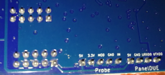
    pinout of TEMP_DB on Maestro

    Scheduled Pinned Locked Moved
    Duet Hardware and wiring
    3
    10
    319
    Loading More Posts
    • Oldest to Newest
    • Newest to Oldest
    • Most Votes
    Reply
    • Reply as topic
    Log in to reply
    This topic has been deleted. Only users with topic management privileges can see it.
    • Fireflyundefined
      Firefly
      last edited by

      I am connecting an accelerometer to a Maestro following this guide
      https://docs.duet3d.com/User_manual/Connecting_hardware/Sensors_Accelerometer
      the guide tells us what wire # to connect to what on accelerometer but the pins# not shown on the board or Duet Maestro Connections diagram.

      25139b40-c9de-4f7d-b667-afbf2cc69fbb-image.png

      11e5fea6-f4d3-4208-969c-af66f9b23ab4-image.png
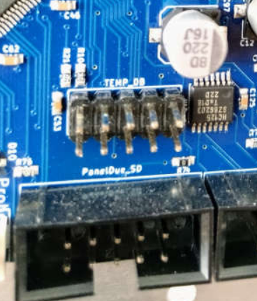
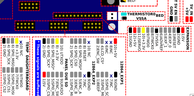
      I don't trust the image because some # start from right to left and others starts from left

      which pin# is 1 and which is pin#2

      I am not using a flat ribbon cable, I know red stripe is pin 1 but I do not know if that goes to top or bottom.

      dc42undefined 1 Reply Last reply Reply Quote 0
      • dc42undefined
        dc42 administrators @Firefly
        last edited by

        @Firefly if you can see the underside of the board then the pins should be labelled there.

        Duet WiFi hardware designer and firmware engineer
        Please do not ask me for Duet support via PM or email, use the forum
        http://www.escher3d.com, https://miscsolutions.wordpress.com

        Fireflyundefined 1 Reply Last reply Reply Quote 0
        • Fireflyundefined
          Firefly @dc42
          last edited by

          @dc42 I really don't want to remove the board from the printer.

          1 Reply Last reply Reply Quote 0
          • Fireflyundefined
            Firefly
            last edited by

            anyone had a Maestro out that can take a picture of the back?

            DIY-O-Sphereundefined 1 Reply Last reply Reply Quote 0
            • Fireflyundefined
              Firefly
              last edited by

              25fe3d09-9d6a-4755-8ac6-9d34f04db21f-image.png
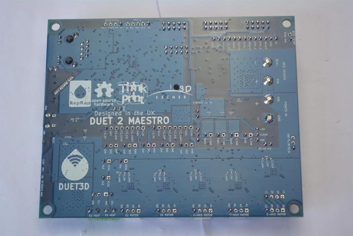
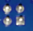
              found this picture, it does not appear to be marked on backside.

              1 Reply Last reply Reply Quote 0
              • DIY-O-Sphereundefined
                DIY-O-Sphere @Firefly
                last edited by

                @Firefly
                427b3bfa-12d4-403c-92d9-1a1ad1decbd9-grafik.png

                Unfortunately no labels can by seen

                (UTC+1)

                Fireflyundefined 1 Reply Last reply Reply Quote 0
                • Fireflyundefined
                  Firefly @DIY-O-Sphere
                  last edited by

                  @DIY-O-Sphere thank you for the picture.

                  1 Reply Last reply Reply Quote 0
                  • Fireflyundefined
                    Firefly
                    last edited by Firefly

                    ok, I was able to confirm with the multimeter, with power off and using continuity to find where GND and 3.3v is and can figure it out from there.

                    and just noticed, looking at the solder joint, the one is square is indicating pin 1.
                    9f3496e3-acf2-46d7-89d3-1fb2c5af1ce1-image.png

                    Fireflyundefined 1 Reply Last reply Reply Quote 1
                    • Fireflyundefined
                      Firefly @Firefly
                      last edited by

                      @Firefly well my attempt to get accelerometer to be recognized failed and now I fear I damaged something.
                      as when I reinstalled the thermocouple daughterboard, I am not getting a temperature reading anymore, then I realized I forgot to stop or remove the input shaping plugin. but still reading 2000C.
                      not sure where to go from here, steps on troubleshooting.

                      1 Reply Last reply Reply Quote 0
                      • Fireflyundefined
                        Firefly
                        last edited by Firefly

                        dunno how or why, but I decided to try moving the thermocouple to second port (from left to right) and its working I didn't even update the code. I never removed the wire I just had the daughterboard unplugged.

                        1 Reply Last reply Reply Quote 0
                        • First post
                          Last post
                        Unless otherwise noted, all forum content is licensed under CC-BY-SA